A friend asked me how I did this, so I made this tutorial for her. Not to let the work go to waste, I am posting it here

Ok, so to start, I took an old cooler, the kind with wheels because it was kind of cracking and I've found that when I go to the beach, it's too heavy to carry and it just sinks into the sand anyway, so I sacrificed it for an incubator
This part is much like any other home built incubator. There are many ways to skin this cat, and you'll want to modify it to what you have available in your home.
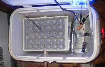
You can see here how it was sort of set up previously in this picture:
(note: I find a 40 watt candelabra bulb is just the right size, but I do have to put a blanket on top of my 'bater in cold weather)
You can enlarge the pictures by clicking on them")
So here, I have all my fans hooked up to an old transformer plug. I can't exactly remember what it originally went to, but basically if you look at it you can see the output is 12 V and 1 amp. A computer fan (small) sucks up about 300 mA (milliamps) and of course 1000 mA is 1 Amp. This means I can hook up 3 fans on this plug and not overload it, all will draw 12 volts. However, these fans can run at 5-7 volts as well. Most cell phone plugs are 5-7 volts, you just have to hook up the correct wire. You would hook up the yellow wire on the fan to the power wire of the plug if you want 12 volts, and the red wire to the power for 5-7 volts ( I know it sounds backwards, but that's how it works
)
The other thing you have to be sure of is that the output is DC, so above you can see it says 12VDC "Volts Direct Current". These fans run on DC current and by the way, 1 fan is plenty, I just wanted to use all my extra fans, LOL. If the plug says AC, it's the wrong type of current.
Ok, so that's how you do the fan
Now I'll go back to showing you the rest of the setup....
( Note, I put in a plastic 1/2" tube through the drain hole to add water with out opening the lid)
On top of the dish which will contain water, I put a layer of hardware cloth that also covers the lightbulb in case a chick gets loose, but really, this isn't necessary with my setup because I'll have another layer of hardware cloth laying on top of the tray when I lay them out to hatch. It's too hard to pull out the tray, which was the original plan.
I found a wooden container, it used to hold a wooden cake on a tray or something, my daughter's old toy, long lost, and I drilled holes on each side, put in a dowel through the walls of the cooler and into the tray. I glued those two wooden pieces inside the tray to hook between the egg crate cups so the crates won't slip when turned back and forth. The one dowel in front also has a pin hole drilled in from the top of the sidewall of the tray and into the dowel so that I can put a pin (paper clip) in there. That keeps the dowel from rotating inside the hole and not turning the tray yet still allows me to pull the dowel out and remove the tray for clean up. Painting the tray also made it easier to clean afterwards. You can also see I inserted a cardboard "wall" covered in aluminum foil to deflect the heat from the light bulb.
(note that the temperature sensor is laying in the egg crate from a vent hole)
Now I just lay in my egg crates with holes cut out at the bottoms to help distribute heat. I forgot to mention that I also drilled "matching" holes in the wood below.
Now I've got it all set up except the heat monitor. I used to have an electric water heater thermostat, but I just bought an STC-1000 temperature controller off ebay, and I must say, now that I've got it working, it's awesome! It's really working with + 3 degrees celcius. For degrees C, you need 37.5 for Chicken eggs. Basically, I set it now to 37.7, because it doesn't seem to go over that, but rather turns off at that temperature, and it will turn back on at 37.4. So far so good!
Now, all I had was a light bulb, my heating element, and it's cord with two bare wires sticking out of my cooler. I needed to put in the temperature controller. Here is what it looks like:
(note, this picture shows the temp sensor already "plugged in")
Sorry for the fuzzy pictures, I'm not a great photographer
. That is the unit, showing the end piece of the sensor. The other end of the sensor is just two bare wires that are to be inserted as shown into the unit. But I get ahead of myself here....
When you get the unit, it has a back piece on it that you have to take off. Just the one screw in the back... so take it out and the piece comes off.
and here it is off:
Next, I modified this schematic someone did (for refrigeration instead of heat) because it was nice and clear (I still got confused, and had to look at it a few times, LOL - signs I'm getting old)
(forget about the green note there, we're using a simple light bulb, no grounding required)
This does not show the sensor plugged in. This keeps it easier to read. The sensor would simply be inserted into the spot shown and I don't think it matters diddly squat which end goes where, so no worries! This is actually written on the unit, so you shouldn't get too confused.
Basically, you take a regular two pronged power cord. You can use an extension cord that you cut the "female" end off of (the end where you'd plug other things into) or do like I did, and use most of the cord from the light fixture), Next, split the two sections of the non-plug end of the cord down the center so you've turned it into two "pigtails" Then take two 6+" sections of the same kind of cord (I used some I had laying around, but you could have just cut two 6+" pieces off the extension cord before the above step) , split the ends the same way and expose the wire inside.
Now, cords come with one side marked. Usually, it's with ribbing on one side (little molded lines going along one side of the cord) Or else there will be a black line (for light cords) or white line (for dark cords). In my pictures, the dark cord had ribbing, the yellow chord had a black line. The side with this marking is NEUTRAL. The plain side is HOT. That is the standard.
Now take the hot side pigtail of the cord with the plug on it (DO NOT PLUG INTO AN OUTLET UNTIL COMPLETELY FINISHED) and connect it to the two other sections of cording's hot line. Twist the wires together nice and secure, then cap it with an electrical wire nut. These nuts twist on and anchor themselves onto the exposed wires. You'll feel it grab, it should be pretty secure, though when all of this is finished, you could wrap electrical tape (a rubbery tape, comes in many colors) around everything as an extra measure of security (so it doesn't accidentally fall apart)
Now do the same thing with the neutral end (with the marking)
Now you should have 4 exposed wires. One of the "hot" wires (no marking) goes into slot #1. You will see a tiny flat head screw viewing from the top of the STC-1000 device. Make sure it's loose, and looking from the back, you'll see "jaws" that you can insert the wire into. You'll want to trim the wire end to a nice short but sufficient length (after twisting it tight if you don't have solid wire). You can do this by trying it out for size. Just insert it into the jaws and see how far it goes in, then trim the wire until the insulation just touches the outside, but the wire still sits fully inside the "jaws". Next you tighten the tiny screw which tightens the "jaws" and you should feel the wire firmly held in place.
The next hot wire goes into #5, for the heating element. We won't be using the cooling element.
(note: in this picture, you see the hot and neutral plugged into 1 & 2, the sensor in 3 & 4 and the hot in #5)
Now the next wire is the "hot" wire from the light bulb. Insert it in #6. The "neutral" wire from the light bulb will be connected to one of the neutral pig tails, and the last neutral pig tail plugs into the #2 slot.
(note: I'm holding the device upside down from the direction we were working with. #5 and #6 is closest)
At this point I secured the device to my incubator since my wires were too short to set it on top, and proceeded to set the temperature and the variance.
Setting the device:
You do this by hitting S for at least 3 seconds, then you'll be in F1 mode (set temperature) Use the ^ or down arrow to go to F2 (set variance) F3 (set compressor delay, not used) or F5 (temperature calibration value [defaults to 0, which is temp of very icy water, if you want to see how accurate it is) Remember it only does celcius.
So to set the temperature, you first hit S for 3 seconds. You are now in F1 mode, hit S again and hold it while you push the up or down arrow to set your desired temperature, then when you have it, hit the on/off button (the circle with a line on top) to save it (just one quick press) I set it to 37.7 because that is where the device shuts off, and I wanted it a little higher than 37.5 so it averages 37.5 (sorta)
For the variance, it goes down to .3 degrees, but is set to .5 degrees, so again you press and hold the S button for 3+ seconds, let it go and press the up arrow for F2, then press and hold the S button again and use the up and down arrows to choose what variance you want, and set it with the on/off button.
There you have it, you're ready to go! It is working AWESOMELY! Wish I never bothered with the water heater thermostat! If only it kept track of the humidity, I'd be in heaven!

Ok, so to start, I took an old cooler, the kind with wheels because it was kind of cracking and I've found that when I go to the beach, it's too heavy to carry and it just sinks into the sand anyway, so I sacrificed it for an incubator

You can see here how it was sort of set up previously in this picture:
(note: I find a 40 watt candelabra bulb is just the right size, but I do have to put a blanket on top of my 'bater in cold weather)You can enlarge the pictures by clicking on them
So here, I have all my fans hooked up to an old transformer plug. I can't exactly remember what it originally went to, but basically if you look at it you can see the output is 12 V and 1 amp. A computer fan (small) sucks up about 300 mA (milliamps) and of course 1000 mA is 1 Amp. This means I can hook up 3 fans on this plug and not overload it, all will draw 12 volts. However, these fans can run at 5-7 volts as well. Most cell phone plugs are 5-7 volts, you just have to hook up the correct wire. You would hook up the yellow wire on the fan to the power wire of the plug if you want 12 volts, and the red wire to the power for 5-7 volts ( I know it sounds backwards, but that's how it works

The other thing you have to be sure of is that the output is DC, so above you can see it says 12VDC "Volts Direct Current". These fans run on DC current and by the way, 1 fan is plenty, I just wanted to use all my extra fans, LOL. If the plug says AC, it's the wrong type of current.
Ok, so that's how you do the fan
Now I'll go back to showing you the rest of the setup....
( Note, I put in a plastic 1/2" tube through the drain hole to add water with out opening the lid)On top of the dish which will contain water, I put a layer of hardware cloth that also covers the lightbulb in case a chick gets loose, but really, this isn't necessary with my setup because I'll have another layer of hardware cloth laying on top of the tray when I lay them out to hatch. It's too hard to pull out the tray, which was the original plan.
I found a wooden container, it used to hold a wooden cake on a tray or something, my daughter's old toy, long lost, and I drilled holes on each side, put in a dowel through the walls of the cooler and into the tray. I glued those two wooden pieces inside the tray to hook between the egg crate cups so the crates won't slip when turned back and forth. The one dowel in front also has a pin hole drilled in from the top of the sidewall of the tray and into the dowel so that I can put a pin (paper clip) in there. That keeps the dowel from rotating inside the hole and not turning the tray yet still allows me to pull the dowel out and remove the tray for clean up. Painting the tray also made it easier to clean afterwards. You can also see I inserted a cardboard "wall" covered in aluminum foil to deflect the heat from the light bulb.
(note that the temperature sensor is laying in the egg crate from a vent hole)Now I just lay in my egg crates with holes cut out at the bottoms to help distribute heat. I forgot to mention that I also drilled "matching" holes in the wood below.
Now I've got it all set up except the heat monitor. I used to have an electric water heater thermostat, but I just bought an STC-1000 temperature controller off ebay, and I must say, now that I've got it working, it's awesome! It's really working with + 3 degrees celcius. For degrees C, you need 37.5 for Chicken eggs. Basically, I set it now to 37.7, because it doesn't seem to go over that, but rather turns off at that temperature, and it will turn back on at 37.4. So far so good!
Now, all I had was a light bulb, my heating element, and it's cord with two bare wires sticking out of my cooler. I needed to put in the temperature controller. Here is what it looks like:
(note, this picture shows the temp sensor already "plugged in")Sorry for the fuzzy pictures, I'm not a great photographer

When you get the unit, it has a back piece on it that you have to take off. Just the one screw in the back... so take it out and the piece comes off.
and here it is off:
Next, I modified this schematic someone did (for refrigeration instead of heat) because it was nice and clear (I still got confused, and had to look at it a few times, LOL - signs I'm getting old)
(forget about the green note there, we're using a simple light bulb, no grounding required)This does not show the sensor plugged in. This keeps it easier to read. The sensor would simply be inserted into the spot shown and I don't think it matters diddly squat which end goes where, so no worries! This is actually written on the unit, so you shouldn't get too confused.
Basically, you take a regular two pronged power cord. You can use an extension cord that you cut the "female" end off of (the end where you'd plug other things into) or do like I did, and use most of the cord from the light fixture), Next, split the two sections of the non-plug end of the cord down the center so you've turned it into two "pigtails" Then take two 6+" sections of the same kind of cord (I used some I had laying around, but you could have just cut two 6+" pieces off the extension cord before the above step) , split the ends the same way and expose the wire inside.
Now, cords come with one side marked. Usually, it's with ribbing on one side (little molded lines going along one side of the cord) Or else there will be a black line (for light cords) or white line (for dark cords). In my pictures, the dark cord had ribbing, the yellow chord had a black line. The side with this marking is NEUTRAL. The plain side is HOT. That is the standard.
Now take the hot side pigtail of the cord with the plug on it (DO NOT PLUG INTO AN OUTLET UNTIL COMPLETELY FINISHED) and connect it to the two other sections of cording's hot line. Twist the wires together nice and secure, then cap it with an electrical wire nut. These nuts twist on and anchor themselves onto the exposed wires. You'll feel it grab, it should be pretty secure, though when all of this is finished, you could wrap electrical tape (a rubbery tape, comes in many colors) around everything as an extra measure of security (so it doesn't accidentally fall apart)
Now do the same thing with the neutral end (with the marking)
Now you should have 4 exposed wires. One of the "hot" wires (no marking) goes into slot #1. You will see a tiny flat head screw viewing from the top of the STC-1000 device. Make sure it's loose, and looking from the back, you'll see "jaws" that you can insert the wire into. You'll want to trim the wire end to a nice short but sufficient length (after twisting it tight if you don't have solid wire). You can do this by trying it out for size. Just insert it into the jaws and see how far it goes in, then trim the wire until the insulation just touches the outside, but the wire still sits fully inside the "jaws". Next you tighten the tiny screw which tightens the "jaws" and you should feel the wire firmly held in place.
The next hot wire goes into #5, for the heating element. We won't be using the cooling element.
(note: in this picture, you see the hot and neutral plugged into 1 & 2, the sensor in 3 & 4 and the hot in #5)Now the next wire is the "hot" wire from the light bulb. Insert it in #6. The "neutral" wire from the light bulb will be connected to one of the neutral pig tails, and the last neutral pig tail plugs into the #2 slot.
(note: I'm holding the device upside down from the direction we were working with. #5 and #6 is closest)At this point I secured the device to my incubator since my wires were too short to set it on top, and proceeded to set the temperature and the variance.
Setting the device:
You do this by hitting S for at least 3 seconds, then you'll be in F1 mode (set temperature) Use the ^ or down arrow to go to F2 (set variance) F3 (set compressor delay, not used) or F5 (temperature calibration value [defaults to 0, which is temp of very icy water, if you want to see how accurate it is) Remember it only does celcius.
So to set the temperature, you first hit S for 3 seconds. You are now in F1 mode, hit S again and hold it while you push the up or down arrow to set your desired temperature, then when you have it, hit the on/off button (the circle with a line on top) to save it (just one quick press) I set it to 37.7 because that is where the device shuts off, and I wanted it a little higher than 37.5 so it averages 37.5 (sorta)
For the variance, it goes down to .3 degrees, but is set to .5 degrees, so again you press and hold the S button for 3+ seconds, let it go and press the up arrow for F2, then press and hold the S button again and use the up and down arrows to choose what variance you want, and set it with the on/off button.
There you have it, you're ready to go! It is working AWESOMELY! Wish I never bothered with the water heater thermostat! If only it kept track of the humidity, I'd be in heaven!