A Classy A-Frame Chicken Tractor
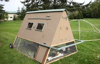
Hi! and welcome to my chicken tractor page. I hope you'll find some interesting ideas and inspiration from my design. I have a couple of innovations that I haven't seen in other designs like a simple "raccoon proof" latch design, adjustable ridge-vent ventilation system, both ends fold down to accept removable nest boxes, and make it easy to clean. Finally, a nice beefy front handle bar that makes moving it around easier, since there's room for three people! This is a big tractor that requires either one big strong guy or two people to move easily.

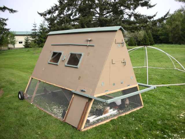
My wife and I wanted chickens for some time. But the devil was in the details. First, we wanted our chickens to have plenty of grass and insects to graze on. Secondly, it rains a lot here in the Pacific Northwest and any fixed coup and run would quickly become a muddy mess in the winter. Also, we just happen to live at “ground zero” for birds of prey in the lower 48 states. You can see more species here than any other place in the country! Needless to say good overhead protection is a must for chickens around here!
General Design Concepts
General Design Concepts
As I worked on this project I realized that chicken tractors have some unique design challenges. They need to be strong and predator proof... yet light enough to move. They should be easy to access and clean. And ideally the design should make efficient use of materials. So I mulled these design constraints over for a couple of years and the following design slowly emerged.
I decided to go with an "A-Frame" design to take advantage of the strength of the triangle. This allowed me to use ripped 2x4s (1.5"x1.75") for all the structural framing, and eliminate the need for most roofing materials which really helped keep the weight down. I tried to desi
gn the dimensions to make the best use of materials and eliminate as much cutting as possible. The sides are full sheets of 1/4" plywood, and the ends can both be cut from a single sheet. The bottom is a full sheet of 3/8" plywood. All the structural members for the base, legs, and handle are cut from pressure treated lumber as they will be exposed to a lot of moisture in our climate. .The 1/4" plywood sheathing added complications to the design since it's not very structural and had to be reinforced along all the door edges to add stiffness and depth to hold fasteners. I used it because I wanted to use up scrap materials I had laying around. I think using 3/8" sheathing throughout would simplify things without much net weight increase I built this unit for approximately $85 - mostly for hardware related items. If you build it from all new materials the cost would probably be closer to $200.
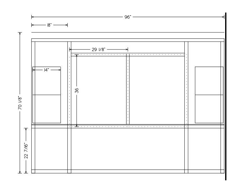
The Basic Plans
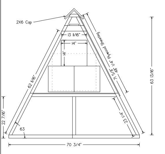
This is the basic sketch of the design. It does not have all the little details like windows, sliding side panels or front handle bar because those were added ad-hoc as the design evolved. I'll try to pick up those details in the descriptions below.
Side View
End View
End View
Basic Construction Steps
Base
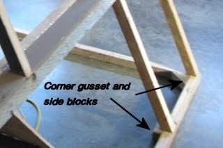
You'll need (2) 8 foot 2x4's for the base. Rip one in half for the sides. Cut the second one to length for the front and back before ripping it in half - you'll need the spare 2x4 material to make the gussets. Lay the pieces out with the wide sides facing up/down and secure them with 3" deck screws. Now cut (4) triangular corner gussets from the spare 2x4 and secure them in the corners with deck screws and exterior grade glue - I like Gorilla Glue. Now cut (4) more straight pieces for base support of the interior trusses. and secure them to the interior sides. Make sure the base is square by checking the diagonals and let the glue set up. Note: If you used pressure treated wood you should consider treating all the cut sides with some wood preservative.
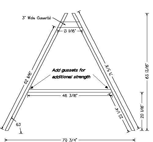
Trusses
Trusses
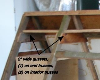
There are (4) triangular trusses - 2 on the ends and 2 interior ones. Each truss requires 1.5 2x4's (ripped in half) plus some 3/4" material for the top gussets and ideally some 1/4" material for gussets to strengthen the bottom joints (only install bottom joint gussets on one side of the trusses as they will interfere with the bottom door support later). I built them as follows. I cut enough material to build one truss. I dry fit all the pieces and double checked the fit. Make sure the tops of the struts are exactly even! I butted mine up against a stop block when I did the layout. Then I assembled that truss using waterproof glue and staples on the gussets. 3" deck screws were also used to secure the bottom support. Once the first truss was completed, I ran some masking tape underneath it and marked some outline marks on it to create a layout template for the remaining trusses. This allowed me to quickly and identically layout the remaining trusses. Then I cut all the remaining pieces and quickly built them assembly line style. Once all four trusses are complete, toenail or screw them into place on the base piece. If you used gussets on the bottom joints, watch which way they go! Gussets on the end trusts must face inside and gussets on the interior trusts must face away from the doors so they won't interfere with the bottom door support later.
Ceiling
The ceiling is a piece of 1/2" to 3/4" plywood or lumber that sits on top of the top truss gussets. Just cut it to width and secure it to the top gussets. Do not notch around the trusses - you want that gap between the outside sheathing and ceiling piece for ridge ventilation!
Remaining Substructure
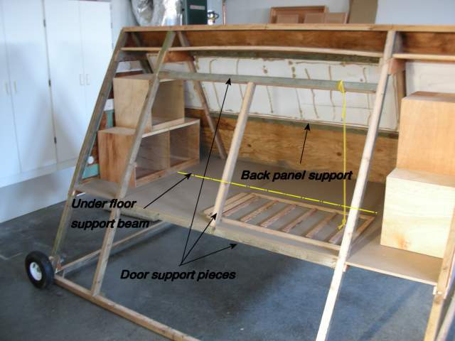
Now cut and install the remaining support pieces. First the bottom and top supports for the doors. Then the center support for the doors. Add a back panel support beam half-way between the top and bottom on the back side. And finally a beam to support the floor down the middle. This beam is optional - it will add strength to the floor but will limit the placement of your "drawbridge" bottom door. If you want more flexibility with placement of this door, consider 1/2" plywood for your floor and skip the support beam.
Top Block
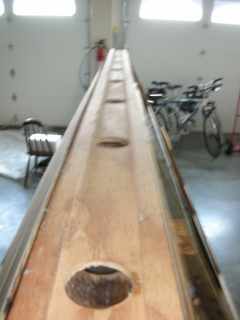
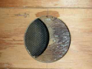
The top block is the piece of wood that rest on top of the four trusses. I used a 2x6 cedar board - but that was probably overkill (it's what I had handy). A 1x6 piece of pine would probably be more than adequate. Ideally the sides should be beveled to 27 degs. to match the slope of the sides, otherwise the sheathing won't fit well at the top. Before installing it you also need to cut 7 (or more?) holes in it for the ventilation system. Be sure and build the top block and the adjustable ventilation system together before installing - you need the pieces to align perfectly. See "Adjustable Ventilation" below for more details. If you don't want the adjustable ventilation, just cut the holes in the top block, maybe add the screening to the underside (probably very important if you don't want wasp, etc in the bay area), and skip the next step.
Adjustable Ventilation!!
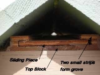
I decided to build an adjustable ridge-vent ventilation system because I could not get any good solid answers to the amount of ventilation required. This way I can experiment and hopefully fine tune things based on the season. This system should be a passive system that works as follows. Warm, moist air rises along the slope of the sides into a smaller and smaller area. This should create somewhat of a venturi effect. The air then moves between the approx. 3/4" gap between the ceiling piece and the side sheathing and moves into the bay area above the ceiling and through the holes in the top block, to the outside airspace under the ridge cap. The holes in the top cap are adjustable due to a matching sliding piece. Fresh air enters from 3 vents on each end and the various small cracks in the structure. Before putting the sliding piece on, put some beeswax or other friction reducer on the top of the top block to aid sliding. Also, an enhancement I did not do would be to extend the sliding piece a few inches and add a finger hole and scale along the side to make adjustments easier.
Top Block
The top block is the piece of wood that rest on top of the four trusses. I used a 2x6 cedar board - but that was probably overkill (it's what I had handy). A 1x6 piece of pine would probably be more than adequate. Ideally the sides should be beveled to 27 degs. to match the slope of the sides, otherwise the sheathing won't fit well at the top. Before installing it you also need to cut 7 (or more?) holes in it for the ventilation system. Be sure and build the top block and the adjustable ventilation system together before installing - you need the pieces to align perfectly. See "Adjustable Ventilation" below for more details. If you don't want the adjustable ventilation, just cut the holes in the top block, maybe add the screening to the underside (probably very important if you don't want wasp, etc in the bay area), and skip the next step.
Adjustable Ventilation!!
I decided to build an adjustable ridge-vent ventilation system because I could not get any good solid answers to the amount of ventilation required. This way I can experiment and hopefully fine tune things based on the season. This system should be a passive system that works as follows. Warm, moist air rises along the slope of the sides into a smaller and smaller area. This should create somewhat of a venturi effect. The air then moves between the approx. 3/4" gap between the ceiling piece and the side sheathing and moves into the bay area above the ceiling and through the holes in the top block, to the outside airspace under the ridge cap. The holes in the top cap are adjustable due to a matching sliding piece. Fresh air enters from 3 vents on each end and the various small cracks in the structure. Before putting the sliding piece on, put some beeswax or other friction reducer on the top of the top block to aid sliding. Also, an enhancement I did not do would be to extend the sliding piece a few inches and add a finger hole and scale along the side to make adjustments easier.
| 
| 
|
Sheathing
Sides
Each side takes exactly one sheet of plywood. The best way to install it is to mark on the end trusses where you want the top of the sheet to be - just up over the top block. Then measure down 48 inches and set a couple of screws into the end trusses to set the plywood on and hold it in place. Check and make sure it goes down to the bottom of the bottom door support member. Then fix it in place - I used 1/4" crown staples, but other methods are fine too. You may want to cut the door area out of the front piece before installing it. I installed it as one piece and then cut out the door area with a circular saw. Also, when cutting out the door area, you want to be sure and cut the sheathing down the centers of the support framing - that way you have door stops. Otherwise you'll have to add door stops to the inside of the framing. You'll notice that there is a little "bay" between the ceiling piece and the top block piece. If, like me, you want to use this area to hold batteries, automation equipment, etc. you should trim off part of your plywood for that section and attach it separately with screws so it can be easily removed. This will create a seam - but you can caulk it. Also, if you want to add insulation, consider doing the area above the ceiling and the back side before installing the other side... the job will be much easier that way.
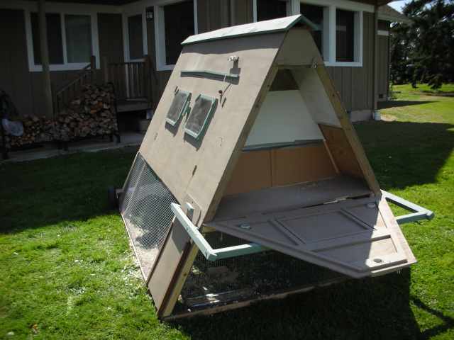
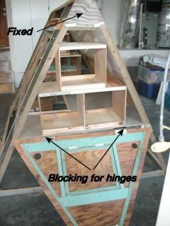
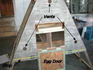
Ends
The ends are cut from a single sheet of plywood and designed to completely open for easy cleaning and removal/replacement of the nest boxes and roost. Note that a small portion at the top is fixed in place to cover the bay area. And there is also a narrow fixed strip at the bottom that covers the framing and provides a flush surface to mount the hinges. Note: If you have to install blocking for installing the hinges, you'll have to cut notches in the flooring for this blocking to recess into. The other option is to hold the flooring back 3/4" from the ends, but that will leave a good sized gap that may create drafts by the nest boxes. I chose to cut out the notches.
Sides
Each side takes exactly one sheet of plywood. The best way to install it is to mark on the end trusses where you want the top of the sheet to be - just up over the top block. Then measure down 48 inches and set a couple of screws into the end trusses to set the plywood on and hold it in place. Check and make sure it goes down to the bottom of the bottom door support member. Then fix it in place - I used 1/4" crown staples, but other methods are fine too. You may want to cut the door area out of the front piece before installing it. I installed it as one piece and then cut out the door area with a circular saw. Also, when cutting out the door area, you want to be sure and cut the sheathing down the centers of the support framing - that way you have door stops. Otherwise you'll have to add door stops to the inside of the framing. You'll notice that there is a little "bay" between the ceiling piece and the top block piece. If, like me, you want to use this area to hold batteries, automation equipment, etc. you should trim off part of your plywood for that section and attach it separately with screws so it can be easily removed. This will create a seam - but you can caulk it. Also, if you want to add insulation, consider doing the area above the ceiling and the back side before installing the other side... the job will be much easier that way.
Ends
The ends are cut from a single sheet of plywood and designed to completely open for easy cleaning and removal/replacement of the nest boxes and roost. Note that a small portion at the top is fixed in place to cover the bay area. And there is also a narrow fixed strip at the bottom that covers the framing and provides a flush surface to mount the hinges. Note: If you have to install blocking for installing the hinges, you'll have to cut notches in the flooring for this blocking to recess into. The other option is to hold the flooring back 3/4" from the ends, but that will leave a good sized gap that may create drafts by the nest boxes. I chose to cut out the notches.
| 
|
Flooring
The flooring takes exactly one sheet of plywood. Since I designed the coup to fully open up for easy cleaning, I put a 1/4" per foot slope in the floor so when it's hosed out or pressure washed the water will easily drain out. I did this by ripping 1 inch thick, 8 foot long strip of wood and placing it across the trusses in the back side. Then I put another 1/2" strip down the middle. The plywood then goes in and rests on these strips. Before installing the plywood, you might want to stain/seal the bottom side for moisture protection - that's much easier to do before you nail it down - unless you want to do a Michaelangelo impression! Another tip is to rip the plywood lengthwise and install one half at a time. That way you can lay each half in and mark where to notch around the trusses. This will also create a small seam down the middle - which helps with water drainage.
Windows
The windows were installed by building frames with a 1/4" rabbit to accept the plexi-glass. I felt plexi-glass was a better choice than real glass. Then the frames were placed on the doors and the interior of the frames was traced on the doors and cut out. The frames were then stapled to the doors from the inside. The plexi-glass was installed using some adhesive caulk and small trim pieces were added across the corners for good measure. Finally, the tops and sides of the frames were caulked to prevent leaks. Tip: The best way to cut plexi-glass is to score it really well (1/8" or better) and snap it!
Wheels
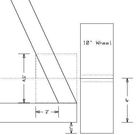
I used 10"x4" wheels from Harbor Freight. With my design these wheels give a 1 inch ground clearance. This worked fine in the garage, but it's marginal in the real world where the ground isn't as flat as concrete. I'm seriously considering going to a 13"x5" wheel (Harbor Freight # 37767-5VGA), That wheel should give a 2.5 inch ground clearance. In retrospect, I think it's better to have the back clearance a little high to start than too low - you can always use some trim to reduce the gap if you need to.
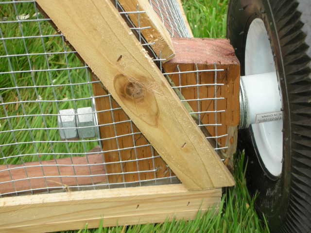
To mount the wheels I had to "square off" the axle area. To do this I took a 4.5"x2" piece of 2x material and bored a 5/8" hole through it half-way up. Then I cut it diagonally to produce two wedges. These wedges were then temporarily mounted to the frame with hot melt glue. This gave me a drilling jig for drilling the axle hole through the truss strut using a 5/8" spade bit. Once the hole was drilled the wedges were removed and cleaned up. Then I applied Gorilla Glue to them, put them back in place and assembled the entire axle system as pictured. The assembly from left to right is "nut, nut, washer, wedge, truss, wedge, washer, washer, wheel, washer". I tightened the nut hard to clamp the wedges in place while the glue dried. Then the nut was backed off to hand tight to reduce friction and allow the wheel to turn. This setting is secured by the second nut, which was applied with some Loctite. The double washers act as slip plates where you can add a lubricant. Keep a block under the back end to take the weight off the wheels until the glue is completely dry.
Sliding Side Panels
*** Coming Soon! ***
Handle Bar
Sliding Side Panels
*** Coming Soon! ***
Handle Bar

The handle bar is made from 2x4 material ripped in half just like the frame. It uses timber joinery type joints to give it great strength for both pulling and lifting. The arms are 36 inches long and attached to frame by 5 inch carriage bolts that go through the trusses. I cut 1" thick spacer pieces that create the gap needed for the sliding panel doors. I cut a 1 inch deep notch in the arms approximately 1 inch from the front ends to accept the cross piece.
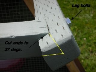
The length for the cross piece should be carefully measured after the arms have been installed. Measure from the bottom of the notch along the bottom side of the arms. The cut the cross piece with a 27 degree angle on both ends. Pre-drill through the arms and the ends of the cross piece and use 3 inch lag bolts to cinch the joints together.
Screening
I used 1/2" hardware cloth for my screening. As built, with the two sliding side panels, one 25' roll of 2' wide material is a perfect fit with virtually no waste. You may need to add additional blocking along the bottom edge of the housing in places to help hold the fasteners. I then made 3 inch thick tack strips from a 1x6 cedar board to help hold the wire mesh good and tight.
Latches
Good predator-proof latches are of course a must. I wanted to design my own that would be simple and inexpensive to build, yet would stump all the raccoons in the neighborhood. These designs are what I came up with.
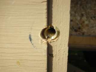
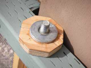
For the front main doors I need something that would keep the doors clamped down tight, but be quick and easy to open. I installed a 3/8" ID brass threaded insert into the center door support post. Then I built my own threaded knob using a 3/4"x 3/8" hex bolt, a few fender washers and some 5 min. epoxy. It's quick and easy to screw this down tight, and it will look nice too once it's painted. I can't imagine a raccoon having the strength to turn this once it's cinched down tight, but I may make a future modification to keep it from being turned.
Screening
I used 1/2" hardware cloth for my screening. As built, with the two sliding side panels, one 25' roll of 2' wide material is a perfect fit with virtually no waste. You may need to add additional blocking along the bottom edge of the housing in places to help hold the fasteners. I then made 3 inch thick tack strips from a 1x6 cedar board to help hold the wire mesh good and tight.
Latches
Good predator-proof latches are of course a must. I wanted to design my own that would be simple and inexpensive to build, yet would stump all the raccoons in the neighborhood. These designs are what I came up with.
For the front main doors I need something that would keep the doors clamped down tight, but be quick and easy to open. I installed a 3/8" ID brass threaded insert into the center door support post. Then I built my own threaded knob using a 3/4"x 3/8" hex bolt, a few fender washers and some 5 min. epoxy. It's quick and easy to screw this down tight, and it will look nice too once it's painted. I can't imagine a raccoon having the strength to turn this once it's cinched down tight, but I may make a future modification to keep it from being turned.
| 
| 
|
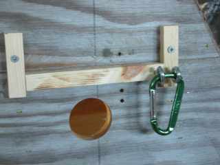
For the ends and egg doors I used the following design. They are just a few pieces of wood, a couple of screws, two eye bolts and a caribiner. The main thing here is too leave the screws a tiny bit loose so the wood pieces can rotate easily. There are 4 of these latches total.
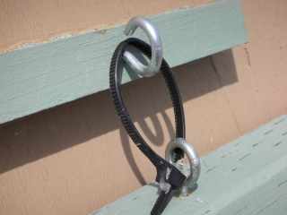
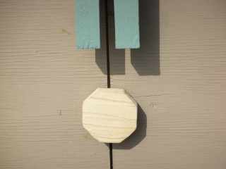
Finally, there is the latch for the sliding panel doors. I wanted something that would keep these doors from being raised. This setup works great and cost next to nothing. I installed 2 eye bolts. Note that the top one has been opened up a little bit by placing it in a vise and using a screw driver. Then I put a zip tie through the bottom eye bolt and through the top. Next, carefully adjust the zip tie so that it will just slip over the top eye bolt when it is pinched together to provide maximum length. Then I locked this setting in place by adding a dab of hot melt glue to the tracks of the zip tie. Simple... yet very difficult for an animal to manipulate. The key is to carefully adjust it so it will not slip off without being pinched closely together.