Automatic pop hole opener
This is not my own idea. We got the idea from a fellow BYCer. We now have two coops (imagine that) and our first automatic door opener was first installed in February of 09. It has been happily pulling open and pushing closed our fiberglass coop door since then without a problem. The instructions are quite easy and can be accomplished by someone with the skill level of an intermediate handy person.
Material list:
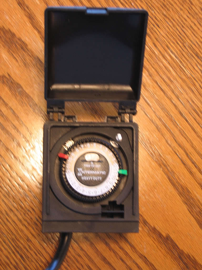
- An outdoor timer (digital would be REAL nice but optional). Goodwill sold us this for $2.00!
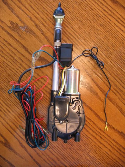
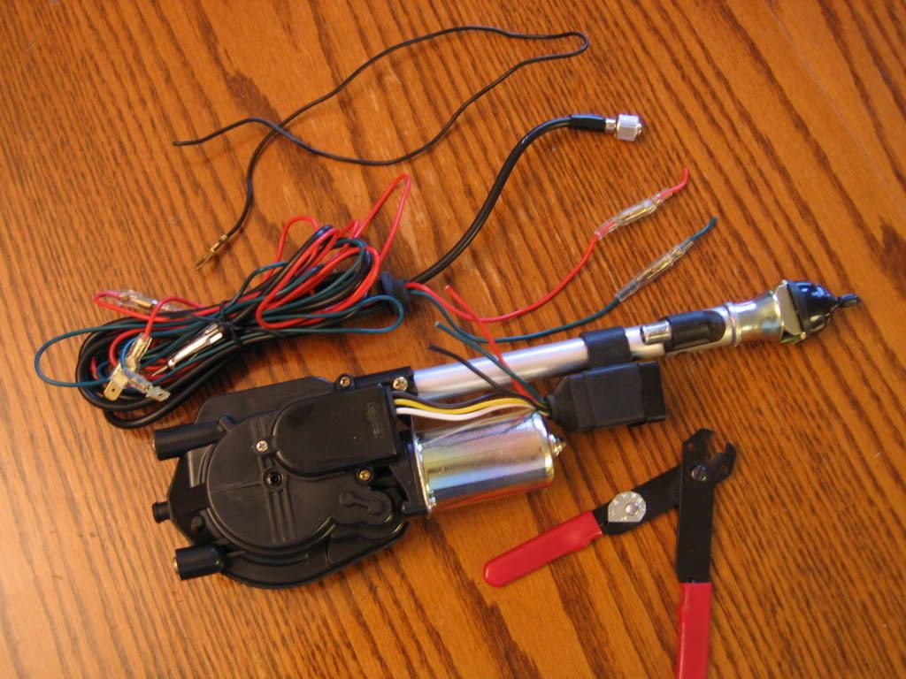
- Automatic car antenna (purchased off eBay new for $18.50 delivered.
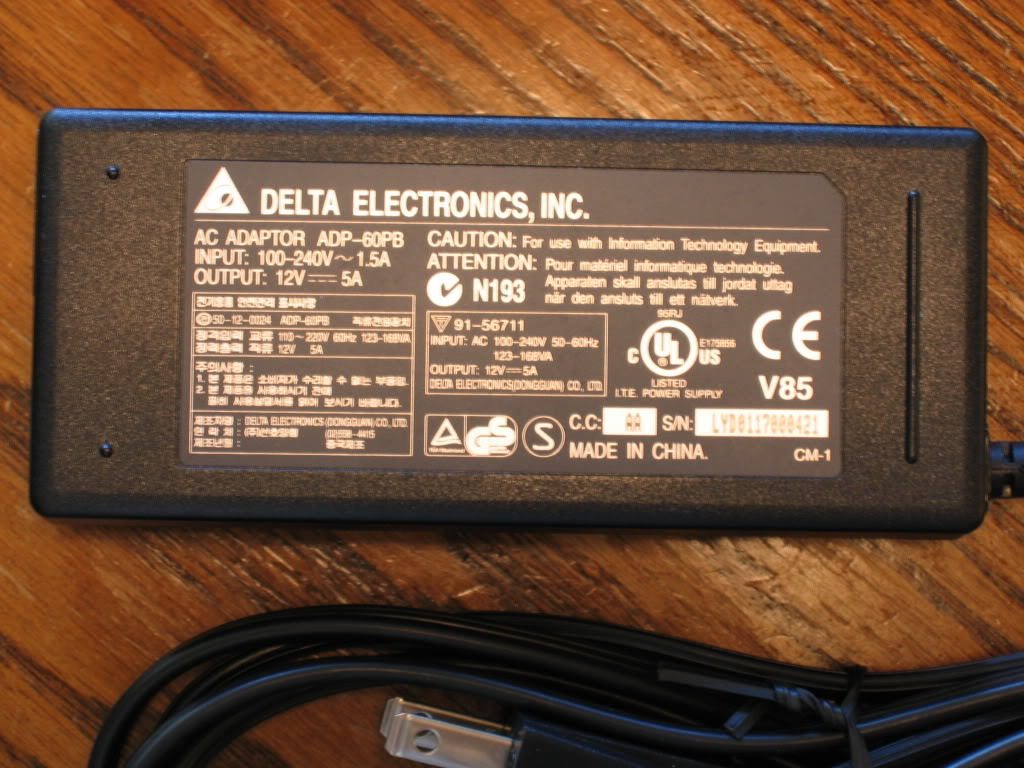
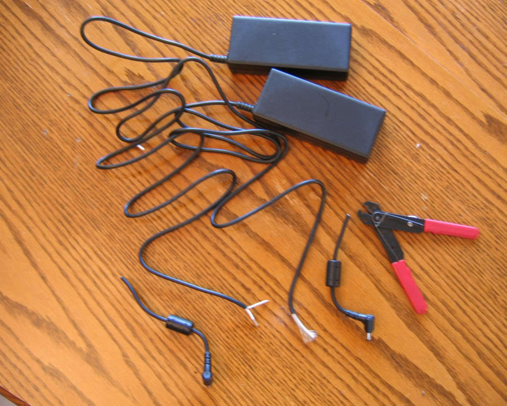
- Two power adapters 12 volt 5 amps min. Think LCD monitor power adapters. I purchased 2, new off eBay for under $20.00 delivered.
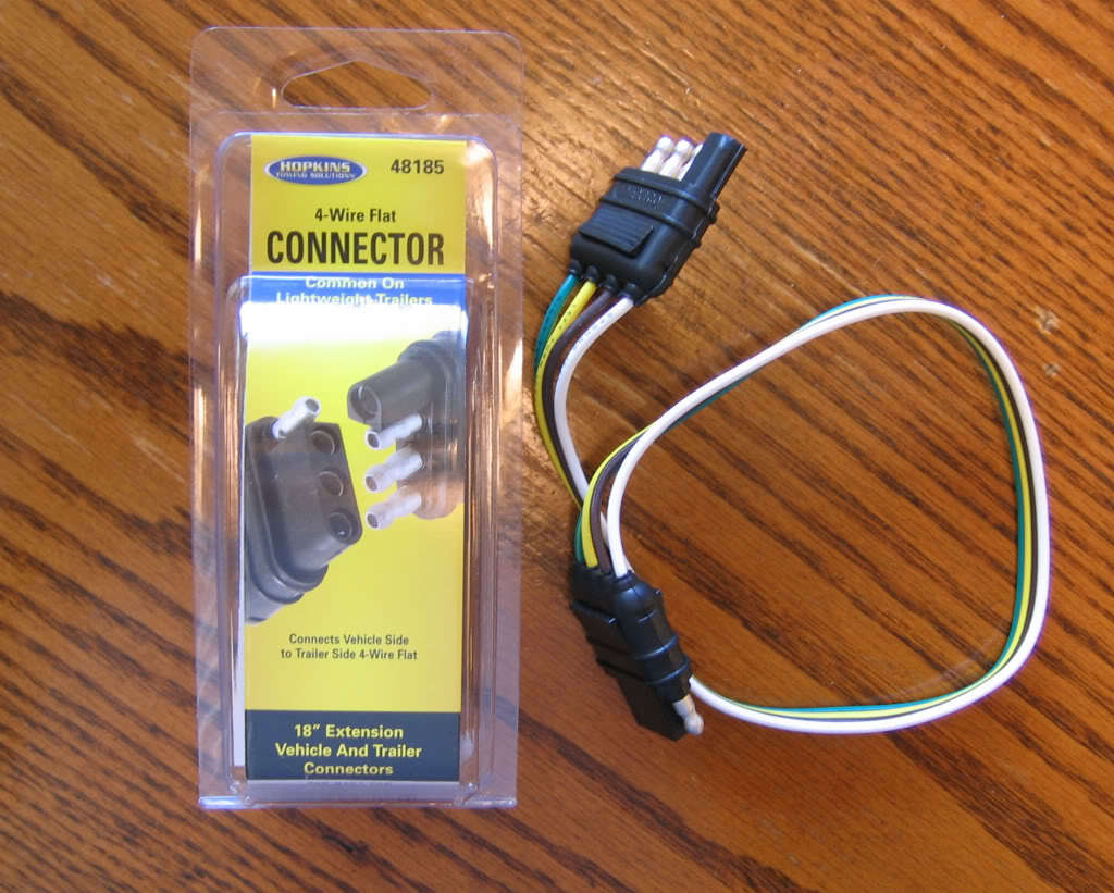
- 3 or 4 flat wire connectors (optional, can be wired, just makes it easier to connect and work with) $3.99 at Walmart.
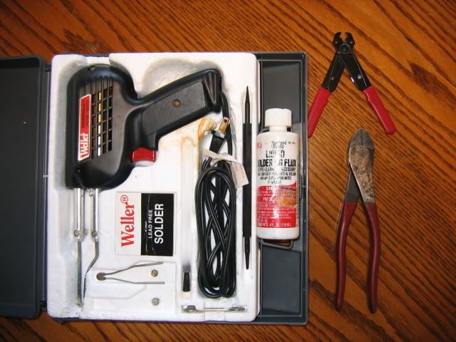
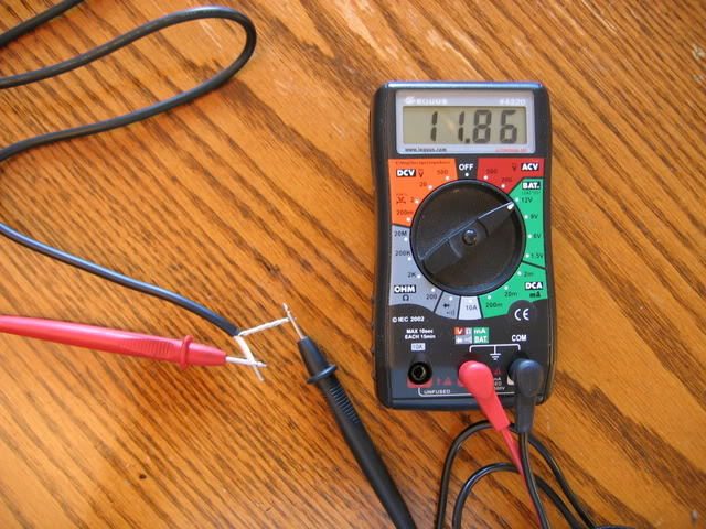
- Soldering kit or wire nuts or crimp connectors. A volt meter of some sort to figure out which is hot and which is ground. Wire cutters and black electrical tape.
- Extension cord if you don't have power to your coop.
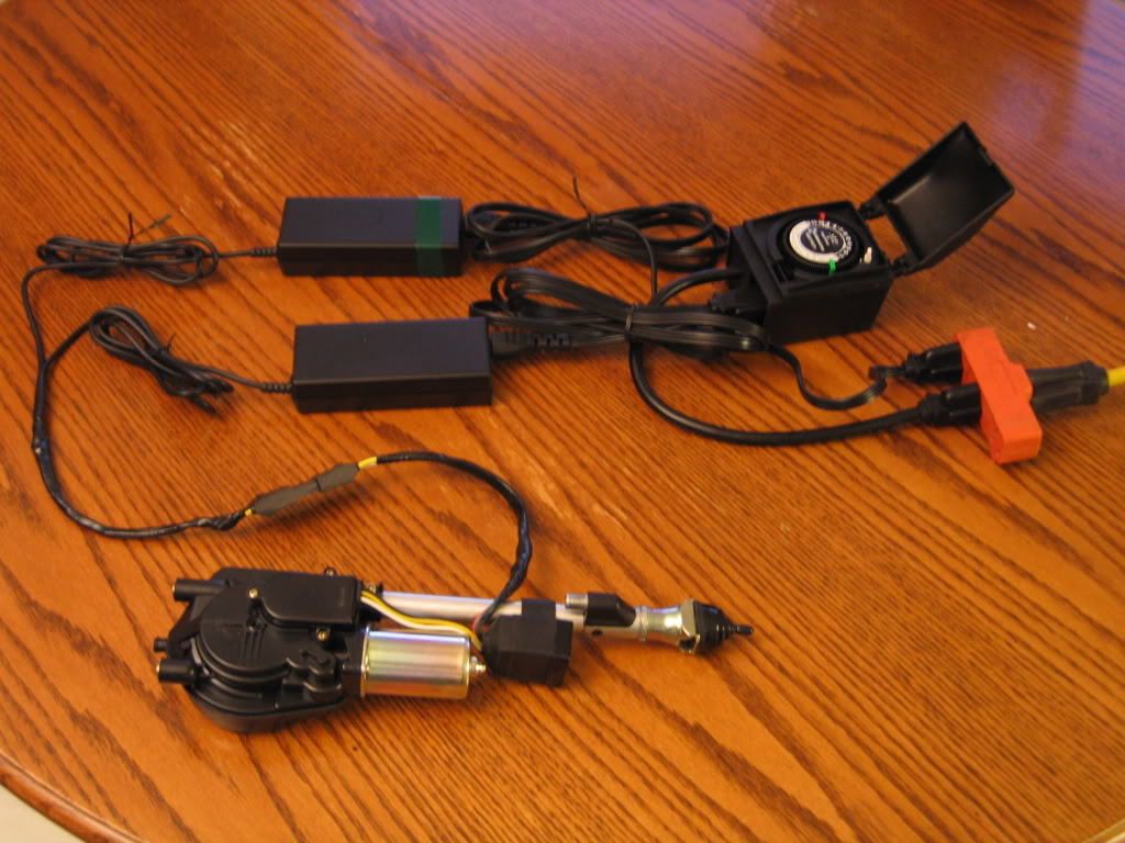
Materials:
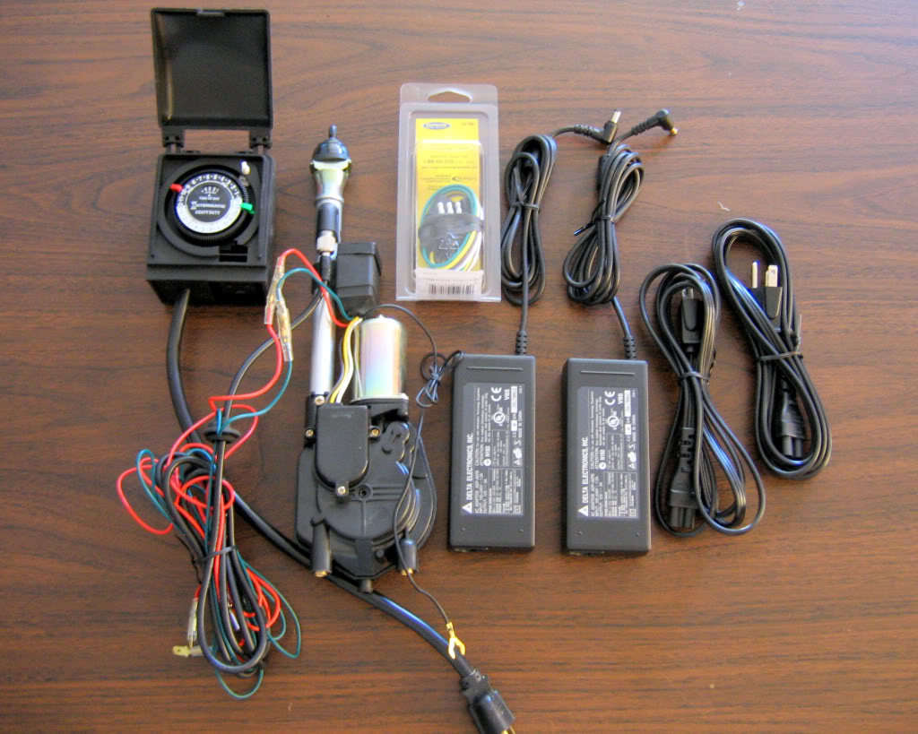
New or used car antenna. One of ours is new and one is used.
The two 12v 5 amp power adapters.
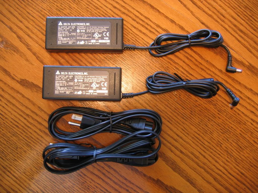
Make sure it is at LEAST 12v 5 amp to meet the power demand of the antenna.
This is a convenience item' this can all be hard wired but it's kind of bulky to move around and work with. This makes it easier to just "plug" in.
Your basic grounded outdoor timer. A digital one would be real nice! Make sure it only has one on and one off per day.
Our soldering kit and wire cutters
Let's get started!
1. Prepare pig tail. You will only need 3 wires so I cut off the extra one, your choice.
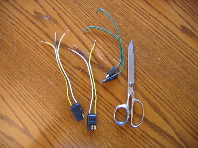
2. Cut off the adapter plugs' ends with wire cutters, strip the ends.
3. Determine which wire on both adapters is "hot" - remember this!
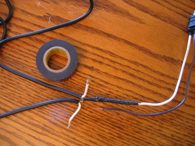
4. The antenna motor requires a common ground to function, so take the two grounds from the adapters and connect them together to the wire on the plug that is going to be ground. I chose the white wire to be the ground color. So now you have the 2 ground adapter wires and the one ground plug in wire all twisted together. At this point you connect them by either wire nuts, crimp connectors. or by soldering them together. I soldered them.
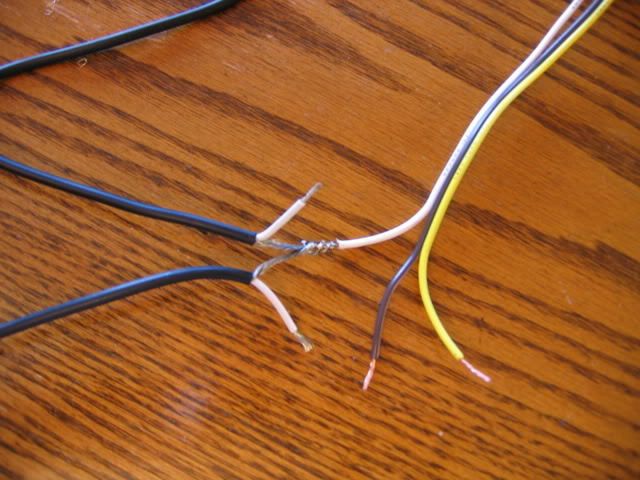
After I soldered the wires I then took the black electrical tape and taped them up.
5. Now select one of the wires on your plug for constant power. Then connect the hot wire from your adapter and connect then in the fashion you chose in the previous step and tape.
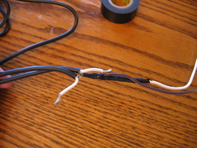
6. Now take your other adapter's hot wire and connect it to your third wire. This will be the on and off wire. Connect them as before.
7. Now you have the two adapters wired to your connector plug and everything is nicely taped. Now you need to verify which wire in the plug is hot and which is ground. As you can see, the male plug end is the ground and the first female is hot.
8. At this point you have to determine which adapter is your constant and which is the on and off and mark it. I put a green band of tape on the adapter that is the on and off adapter; also, if using a connector like I did, note the wire color.
To make the antenna function you have to have a constant hot and an on and off. Just think of it like putting your key in the ignition of your car. When there is power the antenna goes up and when there is no power the antenna goes down.
In this pic you can see my on and off adapter is marked in the green tape. As you can see the male plug is the ground and the second female is hot.
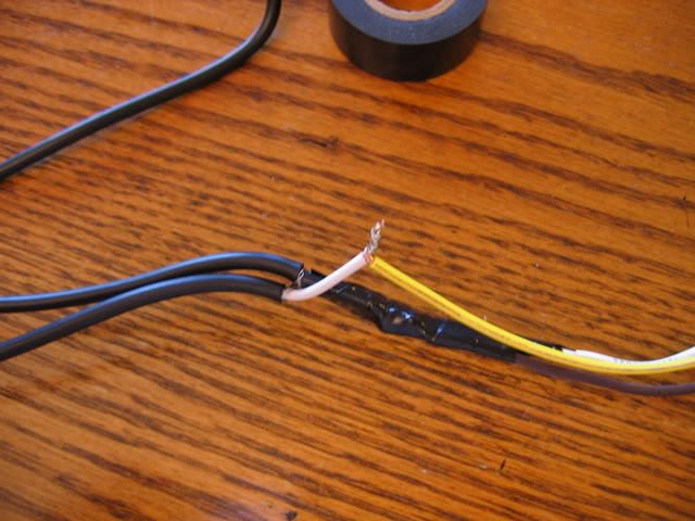
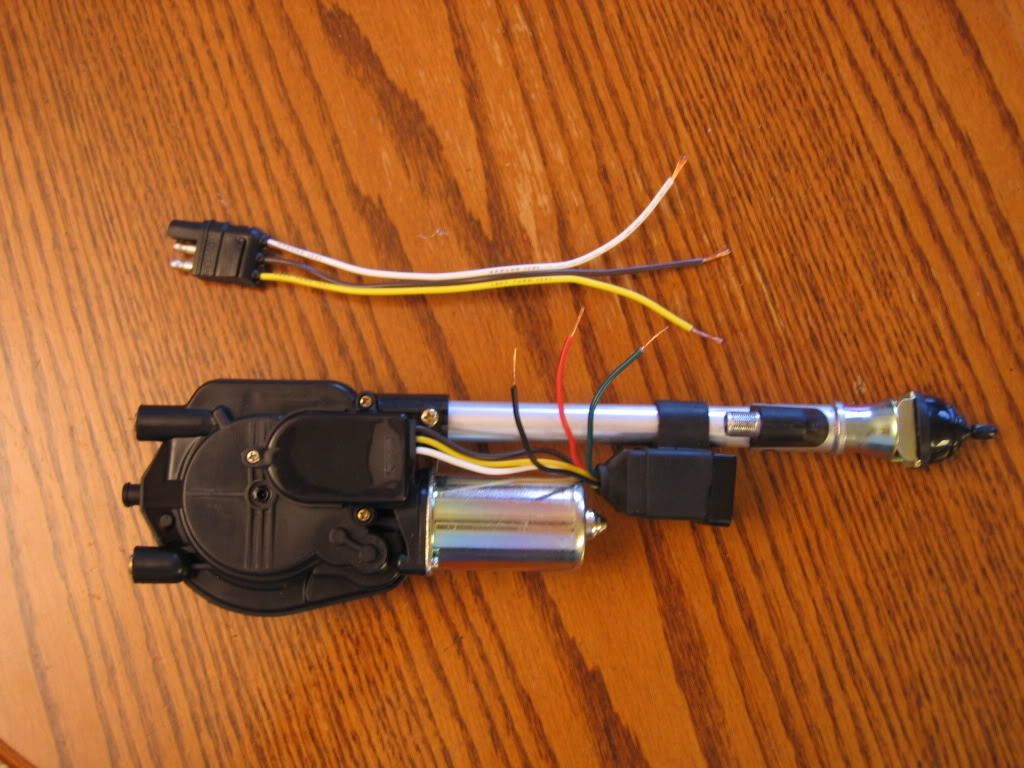
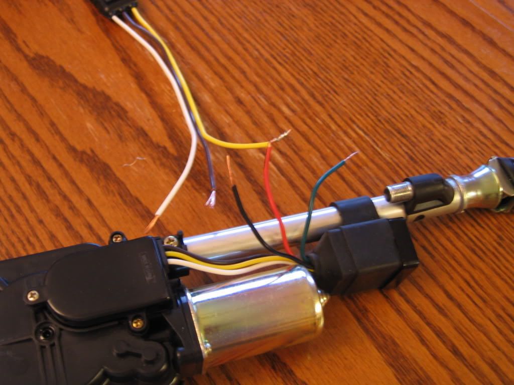
9. Now we are going to do the same thing to the antenna - connect the 3 wire plug connector to it, just like the adapters. Cut off all the wires to a manageable length (optional, but makes things easier).
This is what it should look like before connecting everything.
10. Make the connection for the constant hot wire and tape.
11. make the connection for the on and off hot wire and tape, color noted from step 8.
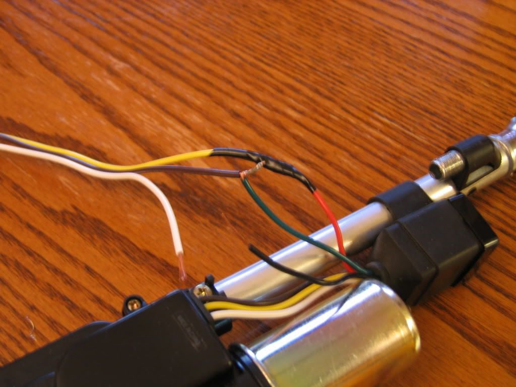
12. Make the connection for the common ground wire and tape.
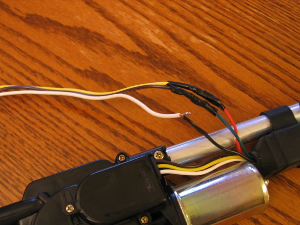
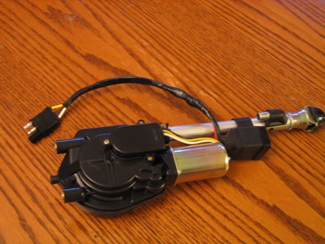
This is what mine looked like with wires all connected, taped, and ready for action.
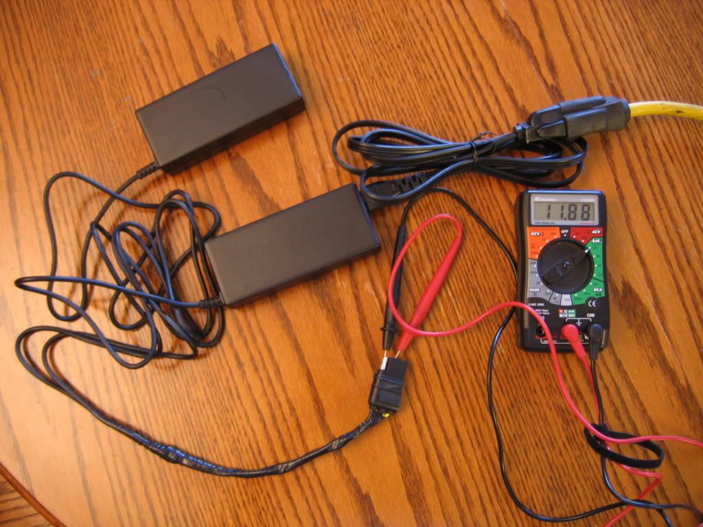
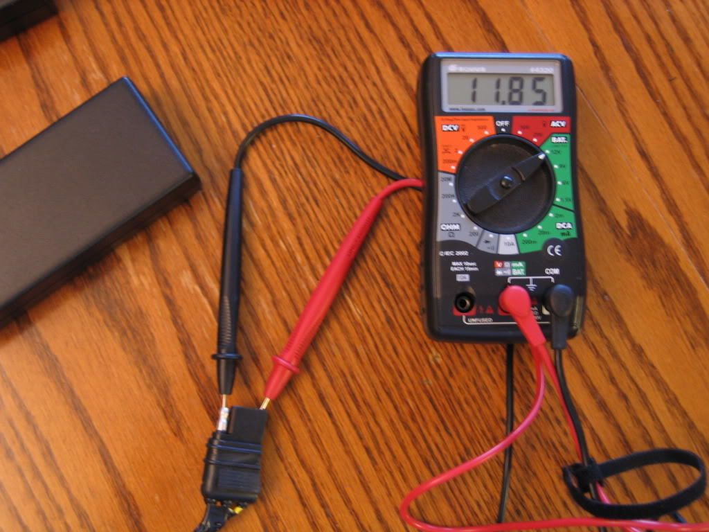
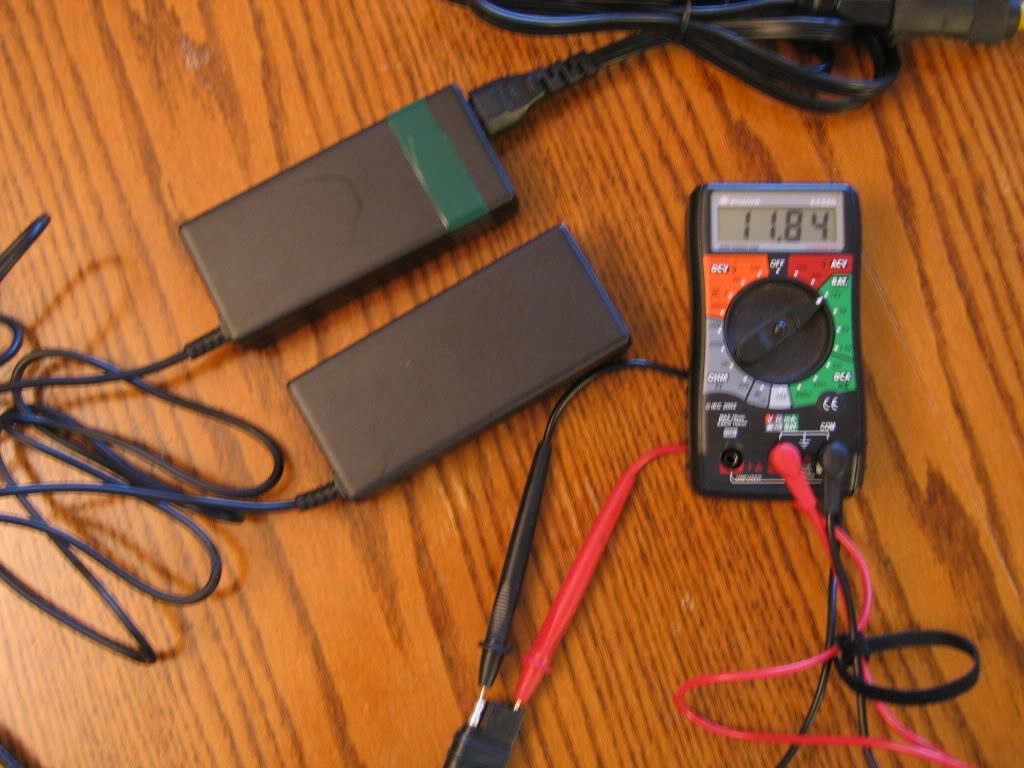
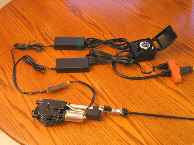
13. Now we are all wired up and ready for a trial run. The brick with the green band is plugged into the timer in the off position. The second brick is the constant and plugged directly into the power cord.
14. The picture shows that the timer is on and the antenna has extended.
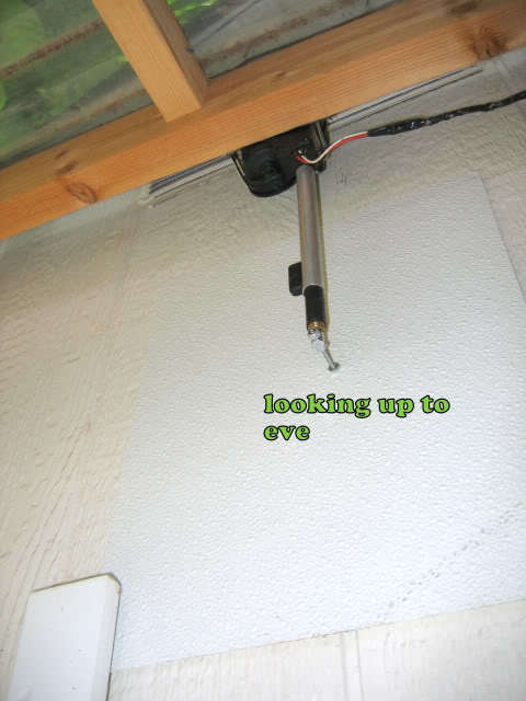
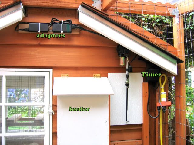
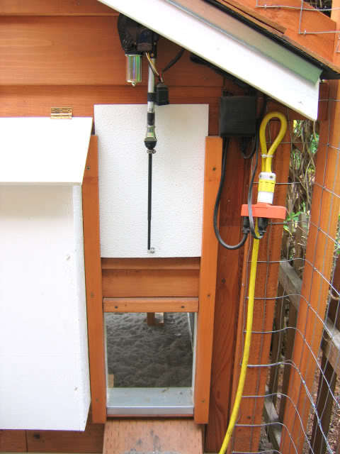
At this point you may want to mount your brick adapters to something for installation convenience. I mount mine to a 1"x4" board with zip ties. Both of mine are mounted guillotine style (up and down) with the antenna motor suspended from above the door. They are each mounted differently to the door itself based on the head size (tip) of the antenna. I used fiberglass bathroom surround material for both doors since I had it on hand from a previous project (chest freezer repair).
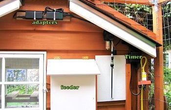
We installed all the hardware in the back of the coop under the eve for weatherization and to be out of sight. You need to keep in mind the antenna extension.
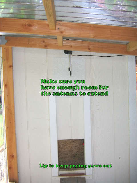
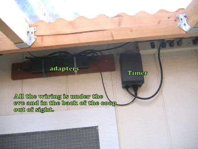
This is the installation of the opener we just made for the "new" coop. This is the back of the coop and you have to be in the run to see it. Most people don't want to go in my run... hummmm.
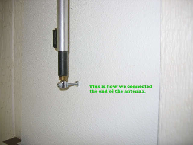
I drilled a small hole in the end of the antenna and put a screw through it.
Well, that's about it. I can't imagine not having an automatic door opener. It makes to coop so much cleaner. The doors are set to open at the crack of dawn and close a half hour after sunset. So my chickens spend no time milling around in the coop waiting for me to open the door, pooping and pooping and pooping....
Good luck!