Linear actuator HELP!

Pics

Ladobaze

Songster
Jan 20, 2020
123
115
106
Lexington, KY
So I’m building an automatic coop door. I bought all the necessary items and put them together (which took every last brain cell in my body). Now it all works EXCEPT, the actuator extends but it doesn’t retract when its supposed to. I switched around the actuator wires and this time it retract but wont extend. WHATS WRONG?! Where should I even look to fix this issue? Uhg.
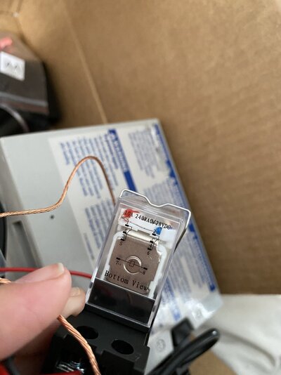
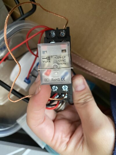
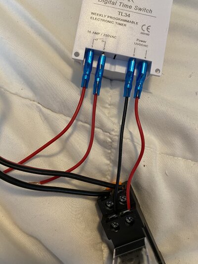
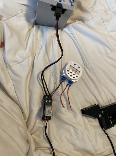
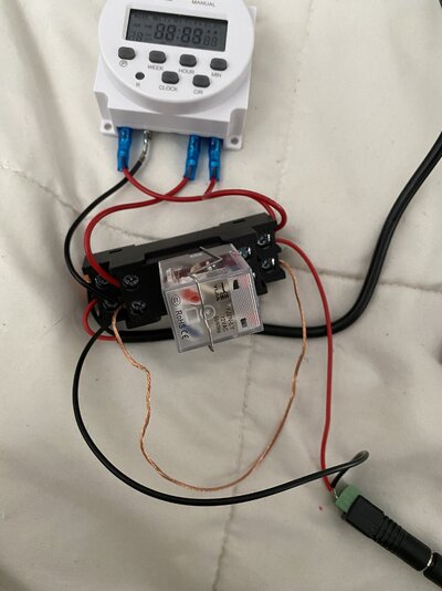
I don’t know if this pic will be helpful but I’ll attach it just in case it is.
 

Attachments

  • 40A34AC1-EA7C-43F5-9048-C2C9540A65DC.jpeg
    40A34AC1-EA7C-43F5-9048-C2C9540A65DC.jpeg
    402.2 KB · Views: 58
Last edited:
It sounds like your relay is not wired correctly. I can't tell from the picture. You just want a simple DC reversing relay. Those actuators are very powerful, are you also putting in a safety switch in case a chicken gets caught in the down stroke? Some of those will cut a chicken in half. I'll post a diagram this weekend. I'm sorry, I don't have it with me.
 
It sounds like your relay is not wired correctly. I can't tell from the picture. You just want a simple DC reversing relay. Those actuators are very powerful, are you also putting in a safety switch in case a chicken gets caught in the down stroke? Some of those will cut a chicken in half. I'll post a diagram this weekend. I'm sorry, I don't have it with me.
That’s what I thought might be the problem. I have a new relay coming just in case. I haven’t got a safety switch (I honestly don’t even know how to do that) however, this actuator moves slower than a heard of snails traveling through peanut butter so hopefully my chickens won’t be too unintelligent! I appreciate your help!
 
Does this help? I saw these and also looked up a diagram online but it is jibberish to me.
I doubt you need a new relay. Can you post a picture of the diagram on the side of the relay?
 

Attachments

  • A0218BA6-F73F-4835-9E51-C1F5F69A3636.jpeg
    A0218BA6-F73F-4835-9E51-C1F5F69A3636.jpeg
    377.1 KB · Views: 28
  • 02D77624-43ED-4838-8F43-4B6BFE844CE5.jpeg
    02D77624-43ED-4838-8F43-4B6BFE844CE5.jpeg
    362 KB · Views: 24
These are separate issues.

I cannot assist with the actuator wiring, good luck.

The last issue above is from the software responsible for routing pages back and forth on the Internet. When this happens to me I reboot the modem for my ISP (Xplornet satellite if it matters) and the problem goes away for awhile.
 
Here’s another link to what’s going on. Maybe it’ll help.
Let's try this...

First, I don't know if the pin outs on the relay match the numbers on your base. I'll get you started using the numbers on your relay. You will need to figure out if the numbers on the base match. You can do that with the continuity setting on a multimeter if you have one.

The positive from your clock goes to 8
The negative from your clock goes to 7
The positive from your battery goes to 6
The negative from your battery goes to 5
You run a short jumper wire from 2 to 3
You run a short jumper wire from 1 to 4
One wire from your actuator goes to 1
One wire from your actuator goes to 2

If it runs opposite of what you want, switch 1 and 2

I have a diagram that includes limit switches in both the up and the down, but it would just confuse you.

Let me know how it goes.
Thank you SO much. Just a quick few questions.
1.) can I use any wire as a jumper wire? Will a piece of positive (red) wire work?
2.) I am including a picture of the numbers on my clock. I believe I have followed instructions so far, sans the jumper wires. What do I do with #1 and #2 on the clock?
 

Attachments

  • F0C142B9-3E0E-4216-A067-DB866DADDA5C.jpeg
    F0C142B9-3E0E-4216-A067-DB866DADDA5C.jpeg
    709.8 KB · Views: 26
Let's try this...

First, I don't know if the pin outs on the relay match the numbers on your base. I'll get you started using the numbers on your relay. You will need to figure out if the numbers on the base match. You can do that with the continuity setting on a multimeter if you have one.

The positive from your clock goes to 8
The negative from your clock goes to 7
The positive from your battery goes to 6
The negative from your battery goes to 5
You run a short jumper wire from 2 to 3
You run a short jumper wire from 1 to 4
One wire from your actuator goes to 1
One wire from your actuator goes to 2

If it runs opposite of what you want, switch 1 and 2

I have a diagram that includes limit switches in both the up and the down, but it would just confuse you.

Let me know how it goes.
Here’s another picture to show the whole set up so far. I REALLY appreciate your help. Thanks so much!
 

Attachments

  • 64E7B7A5-57F9-4DA6-9195-28F5C2705F49.jpeg
    64E7B7A5-57F9-4DA6-9195-28F5C2705F49.jpeg
    467.6 KB · Views: 27

New posts New threads Active threads

Back
Top Bottom