I know this was a while back and I don't wanna read threw all 15 pages but did you ever get your answer?...... easily make this useable for 2 doors. Could you explain how I could do that. What extras would I have to buy other than the linear actuator motor?
Navigation
Install the app
How to install the app on iOS
Follow along with the video below to see how to install our site as a web app on your home screen.
Note: This feature may not be available in some browsers.
More options
You are using an out of date browser. It may not display this or other websites correctly.
You should upgrade or use an alternative browser.
You should upgrade or use an alternative browser.
My DIY Automatic Chicken Door
- Thread starter Tsheaby
- Start date
Very much appreciate your diagrams, pics and vid.
What safety features would you add to these circuits? For an actual implementation would you include circuit breakers, fuses, diodes, something else .. and where?
Thanks again, super helpful

I am writing to let you know I have read you comment and will do a write-up soon. I am not ignoring you in the least. However there are many options when using circuit protection and I want to cover a few of them.Very much appreciate your diagrams, pics and vid.
What safety features would you add to these circuits? For an actual implementation would you include circuit breakers, fuses, diodes, something else .. and where?
Thanks again, super helpful
But out of all of them I will at least give you these little gems.
They are Breaker/Fuses. Called breakers but you can see why I call them that.

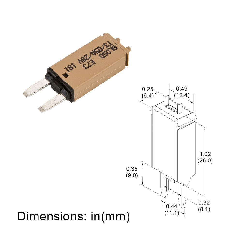
When combined with the holder. They are easy to install and reset if needed.
The drawback is that I can not find the lower 2A and 1A that I would recommend getting. Hard to find, but they do exist. But the 5A should do good for shorts or motor seizing.
The door jamming is the greater issue that will cause damage to circuit and door frame if the fuse rating is too high. The majority of these Linear Actuators are meant for 225lbs, are rated @3A. But if you use a 3A fuse you are waiting for the actuator to be putting the force required to lift 225lbs already. So you are already causing damage. I have tested the actuators to break a 1x4 (what most people would use as rails and it only got up to 1.5 to 1.8 amps before it would break the boards.
So you really would want a 2A breaker or fuse. A slow blow fuse at that. Motors, at start-up, require more amps. So a slow blow fuse make it so makes it so you are not replacing fuses as often while keeping the fuse size as close to where the force to start causing damage is reached. Hope that makes sense.
But don't just go by my tests. Test the amp draw under normal load, and under a load that you think will cause damage to your door frame and coop. Size fuse accordingly.
Placement is going to be determined by your setup.
That all makes sense, really appreciate your reply & thoughts, and look forward to your write-up. Those resettable fuses are cool, didn’t even know they exist.I am writing to let you know I have read you comment and will do a write-up soon. I am not ignoring you in the least. However there are many options when using circuit protection and I want to cover a few of them.
But out of all of them I will at least give you these little gems.
They are Breaker/Fuses. Called breakers but you can see why I call them that …. [snip]
For example, and I guess this is in addition to my fuse/diode question, how can we ensure that the two SPDT timers don’t both send + to the motor at the same time? One thing I think I’ll do is never set them to switch to NO at the same 12-hour clock time (even though the ones I have are on 24-hour clock by default) just in case I don’t have the am/pm set right. But there must be some physical/electrical solution.
Also, and I’m really exposing my electronics noobosity here, I’ve seen a lot of setups using bus bars. I’m planning to instead use a fuse box, which should function essentially the same. Am I wrong here?
In short you don't. Nothing will happen if both the Timers are on at the same time. In fact sending + power to both sides of a motor is often used to power lock/brake a motor. Many people also will have + power to both sides of the motor as the default.how can we ensure that the two SPDT timers don’t both send + to the motor at the same time?
There are times when you want the negative to be use for the limits and minimise the amount of wire energized when the system is not in use.
There are also times where the actuation of the door is done by a large flywheel. If the motor does not have a worm gear box, the motor can slowly drop the door down. Power locking will prevent that.
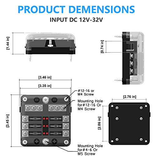
I’ve seen a lot of setups using bus bars. I’m planning to instead use a fuse box, which should function essentially the same. Am I wrong here?
Are you wrong? That all depends on what fuse box you get.
If you get one one of the Marine Style boxes with a negative busbar and the bus fuses then that should be ok. If the fuse block does not have the negative bus then you are still going to add a busbar for the negative.
Just remember to have a board to mount it all on and use a french cleat system to mount that board.
Posts I mentioned french cleats.
Post 1
Post 2
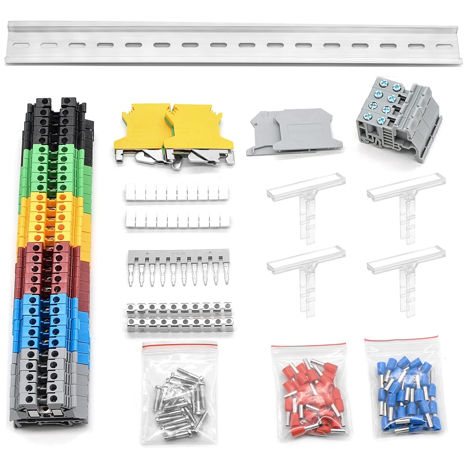
I do have another options for you (will be in the write up with more detail). You can use DIN rail mounted Connector Blocks. The timers I showcase are already DIN rail mountable so why not use that system. They make wire management so much easier.
Option #1
################################################################
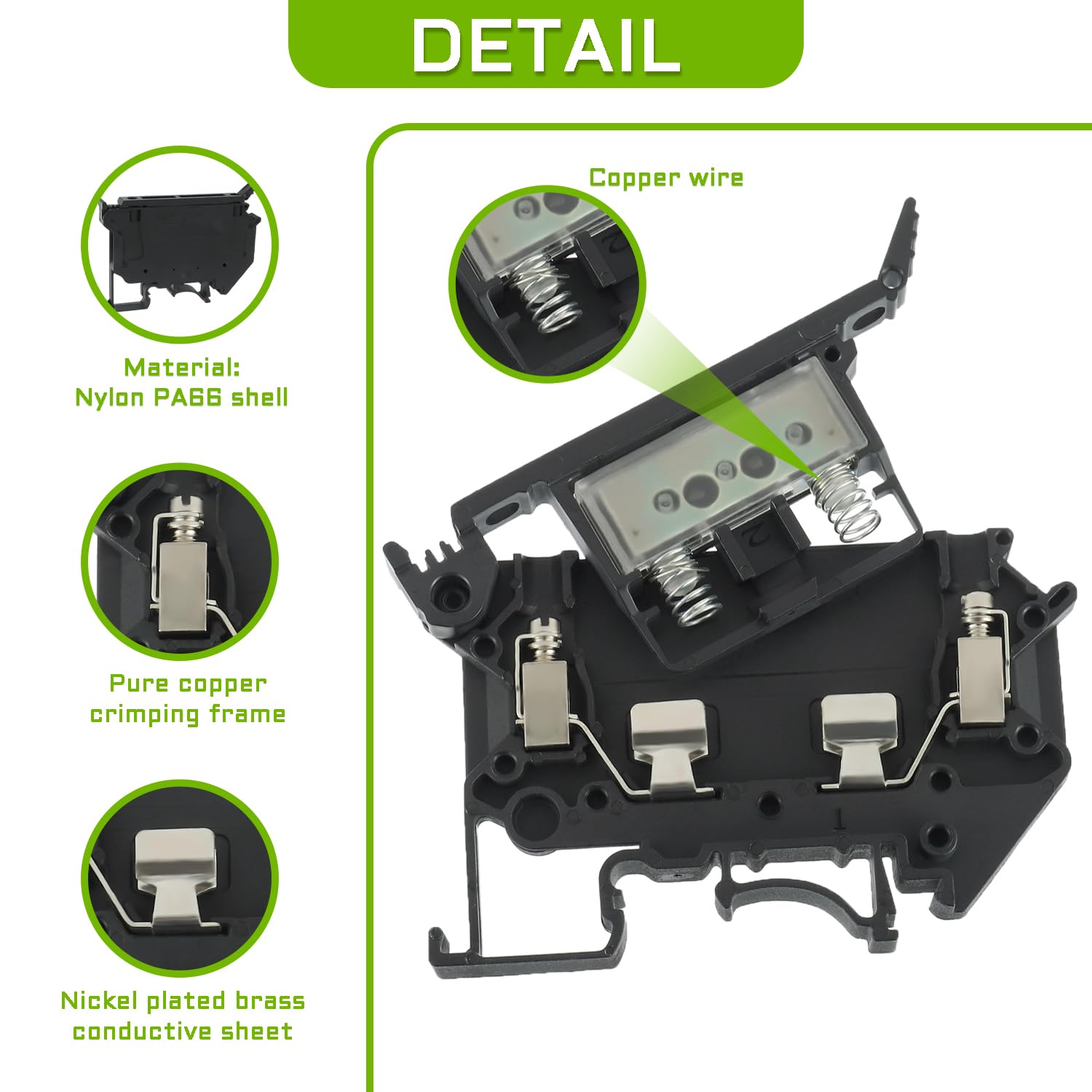
Terminal Block, Rail Type Voltage Terminal, Rail Combined Terminal Block. They come with jumperstrips to combine blocks to make the busbar/power distribution.
##############################################################
Option #2
##############################################################
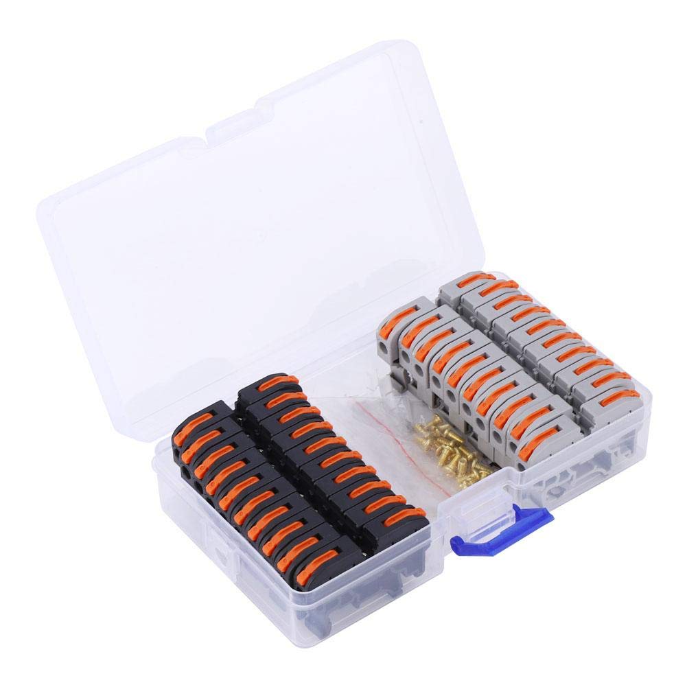
Also an alternative. I use these a lot in projects. Just make sure to test every leaver and every screw & hole when they arrive.
20 pcs Din Rail Connectors Terminal
###############################################################
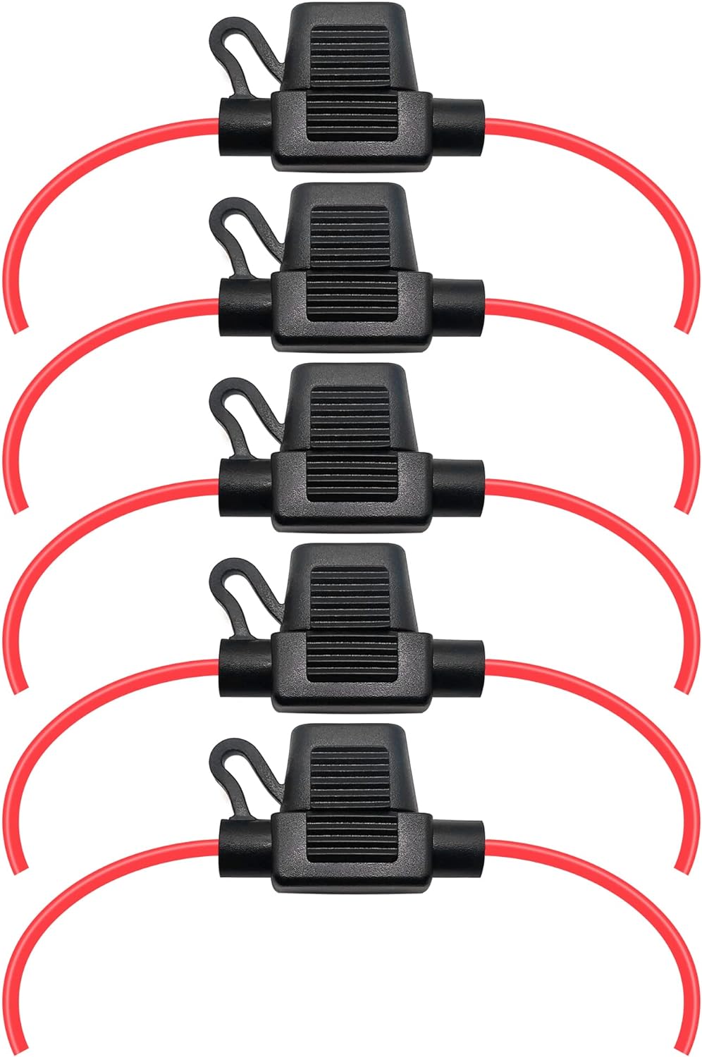
With either of those options you can use the inline fuse holder.
Or DIN rail mounted fuse holders.
LED Indication DIN Rail Fuse Holder Terminal Block
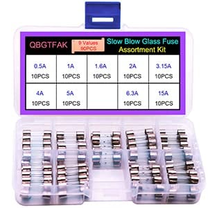
and use with 9 Values 90pcs Slow Blow Glass Fuses Assorted Kit 5x20mm. You won't be able to use the circuit breaker but the fuses are cheap and you can by the assortment with the lower rated fuses.
---------------------------------------------------------------------------------------------
Here is a plane Jane wiring diagram to get you started. It is just a revised diagram of the one I have in post #117
Google Drive will be prompt to you to request for access. Leave message with introduction and link to where you are requesting from. (aka Site, Forum, Thread, Post). No message with link, no access. No "Editor" access will be given.
Why..
A: It lets me know that it is a serious inquiry.
B: You can also comment there too if you need to ask what is the "doohickey" next to the "thingamajig".
C: If changes to diagram need to be made I can easily change it there.
D: If any updates need to be made I can come back and Inform others.
E: This also protects against data mining.
Disclaimer: Some of the links are amazon affiliate links. That may or may not generate a few cents my way. However I try to find the best deal I can find. Tho it is generally to point you in the right direction. Diagrams and Information provided free, use at your own risk. Not responsible for damages or injury.
Last edited:
how can we ensure that the two SPDT timers don’t both send + to the motor at the same time?
It jumped in my head that showing you, not just telling you, is a better way to set your mind at ease. Was going to make a video but realised I already had mentioned this in several videos.
In this video the Single Pole Single Throw Timers and use of external relays is different but the wiring and concept is the same. (In the timers we have been conversing about the relays are internal.) In this video I show that even if both timers are on (both relays are on and +power is going to the motor from both sides of the coil), all that happens is that the motor stops.
Last edited:
@Mouthpear Thanks again for all the info and links!
I altered your limit switch diagram just a bit. Not sure about everybody's implementation, but for me it's useful to have the motor/limit switch complex acting more like a single unit and having only 2 wires between them and the timers ... like the linear actuators do.
S1 & S2 are SPST normally closed momentary pushbutton switches. They have a diode wired between the terminals with the cathode on the motor side. Allows for limit switch action and also allows motor to run at reverse polarity when one switch is open. Got the idea from 2 or 3 actuator manufacturers, e.g. here. The diodes I'm using are IN4001 1A, 50V rectifier diodes. Now to get it mounted and tested.
I'll be making a second one of these, and in that one I'm thinking I will replace the timers with a microprocessor, probably the rasberry pi pico, and an H-bridge motor controller. Should be cheaper and smaller. (In my application smaller size is valuable, not sure about others).
@Mouthpear Thanks again for all the info and links!
I altered your limit switch diagram just a bit. Not sure about everybody's implementation, but for me it's useful to have the motor/limit switch complex acting more like a single unit and having only 2 wires between them and the timers ... like the linear actuators do.
S1 & S2 are SPST normally closed momentary pushbutton switches. They have a diode wired between the terminals with the cathode on the motor side. Allows for limit switch action and also allows motor to run at reverse polarity when one switch is open. Got the idea from 2 or 3 actuator manufacturers, e.g. here. The diodes I'm using are IN4001 1A, 50V rectifier diodes. Now to get it mounted and tested.
View attachment 3779218
You are very welcome.
I like using that method but its use is limited and has only one benefit and that is that it uses less wiring. That is why it is used in Linear Actuators.
On the other hand using them is "more complicated". Most people don't know what a diode is much less know how to use them. Buying them is costly when purchasing singles and then choosing and finding them. Buying in bulk is good when you need lots, but again that's if you need lots and use them all the time. Otherwise a person doing this just once, will end up having a bunch of diodes they may never use.
Not saying that these are altogether a Con/bad thing, but when I design the diagrams, I keep in mind, the fact that many people don't want to deal with that and use as few parts as possible. While also staying away from parts which they may or may not fully understand or comprehend. Plus Most people barely have a proper crimper much less a soldering iron or proper tools to make the connections to involve the diodes.
On that note. I like to use the large schottky diodes most commonly used for solar power panels.
All Pix are of them in "demo mode" (without shielded protection aka heat shrink) for taking pix and showing how to do it.
They are great because the anode and cathode leads are nice and thick.
Easy to........
Solder
Or crimp into a connector
Or place into snap wire nuts
Now here is why I like to use Non-Diode solutions. Simplicity, Versatility and Beneficial.
Simplicity: Anyone that can follow a diagram can do it without trying to figure out how to make the connections. Or need to understand how it works.
Versatility: There are so many different ways to wire the switches (without Diodes) for many different reasons. The following is just one.
You can wire the switches to turn off the timers instead. Saves on power(if that is a concern).
Not only can you wire power direct to the motor, so the larger amp draw is not being put through the limit switches, so a smaller gauge wire can be used (like phone wire). Diagram.
And it power brakes. Which leads to....
Beneficial: There are times where braking the motor is needed. Unless the motor has a "self locking" system like a worm gear drive, the motor can over run because the motor doesn't stop right away. Or it can let the door down. The Non-Diode methods allows for power braking. You lose that ability using diodes. In linear actuators the diodes do not affect the stopping of the motor due to their design.
The Power Wheels motors and gears I used to make this door are an example of this (Video 1).
While they are meant to be strong and fast they do not have the ability to stay in place (Video 2).
The door in the videos is close to 6 lbs. Over time the door can lower. Power Braking stops that from happening and it does not require any extra power. Just the motors own back EMF. The diodes prevent that from happening. Of course this is more needed in designs that use a long lever on motors like windshield wiper motors.
So in my eyes there is only one, really good reason to use the diodes and that is that you only use less wire. While on the other hand there are several good reasons that you might want to not use diodes.
Last. You have your diodes facing the "wrong" direction. While it can work, the common way to do it is the cathode faces the power source. If not, you have to invert your limits. It is fine if you remember to do it, but if you or someone else that uses your diagram forgets, then you can cause damage to whole system.
I made a video showing.....
Top Left the common "correct" way.
Bottom Left is how they are wired in Linear Actuators.
Top Right is yours. Notice it is not the Upper Limit that controls motor when going up but it is the Lower limit, and visa versa.
Bottom Right shows how you would have to place/invert the switches to have it function correctly. May want to make note of that in your comment or diagram.
The Arduino doors I have made, I use a motor shield. Makes it so you can control 4 motors and 2 servos (Or Lights). Pi users call them motor hats. Less wiring and less programming. Speed control is also a bonus.I will replace the timers with a microprocessor, probably the rasberry pi pico, and an H-bridge motor controller.
Last edited:
@Mouthpear
Wow, I guess it's true, there really are a gazillion ways to configure a circuit. Just on the motor/switch side of this little automatic door circuit I can literally think of 32 off the top of my head
 Above are four of them. In each of the above I left out the timer switches, or DPDT relay, or whatever we use to send power from the source to the motor in either polarity; to focus on recent discussion, this is just the motor and limit switch portion. In all four, the power "comes" and "goes" through the wires from the bottom.
I have seen examples of 1, 3, and 4. I haven't seen an example of 2, which is the top left or "correct" one in your video. It wouldn't surprise me to learn that they are all over the place, I just haven't seen it yet.
We can get four more configurations by crossing the input lines of each of the above four, like you did in the bottom right one in your video. It's not clear to me why this matters. I'm not saying there isn't an electrical or mechanical benefit one way or the other, I just don't know what that might be.
Instead of SPST switches we could use SPDT switches, as you did and also as in the examples I linked to above, and we could also use Schottky instead of rectifier diodes ... and we're already up to 32 different configurations.
Considerations or potential issues that come to mind are as follows.
EMP: perhaps this isn't as big a concern as it would be if we were switching with, say, BJT transistors or MOSFETS, but is EMP going to come into play with diodes, and does this depend on diode type and proximity of diode to motor, or with direction of diodes?
Heat: Are some configurations more prone to producing excess heat and result in heat-related failure?
Durability: Are some configurations more durable in the conditions in which we wish to implement them than other configurations from, e.g., heat, cold, moisture, etc.? Cheap motors (relatively), tiny electrical components made of thin metal and plastic ... how will they stand up to weather and moisture?
Capacitance-type of discharge: I don't think I have the correct electrical terminology here, but the idea that a backflow of pressure can occur when a circuit is broken by, e.g. a switch, and electrons flow in another direction. Often handled, if I'm not mistaken, by use of properly placed and sized resistors.
I very much favor a circuit where only two rather than six wires go between the power-sending side (e.g. timers) to the motor/limit switch side. For my particular implementation that is beneficial. Others mileage may vary, but for me it is desirable, largely due to the compact space I'm working with. But also because to me, and perhaps this is simply a matter of taste or the way I happen to be setting it up, it offers a more tidy setup. In addition, I believe any of the two-wire versions vs. the six-wire version will pair more nicely with my intended next microprocessor setup.
So, within the realm of having two wires between timers and motor/switches we have the above possibilities (and others ... we could go on and on). I'm not married to my "1" above, I could happily use your "2", and I might. I also like the "linear actuator" type of "one wire to motor one wire to switches" configurations. You say "2" is "correct" ... if you could elaborate further it might help my understanding and make us better informed at choosing between all these configurations. Especially with regards to the above stated considerations.
I also will definitely be considering the Schottky diodes .. the small rectifier diodes I used are indeed quite tiny, and the larger size might be better when I get to the soldering.
Finally, I didn't indicate in my diagram in post #157 which is the upper or lower limit switch. But, as I said above, it's still not clear to me why that matters.
I will be posting tomorrow. New diagrams and videos.
Till then don't use either of those two examples in 1 and 3.
Last edited:

New posts New threads Active threads
-
Threads with more replies in the last 15 days
-
 Checking-In On Peeps - Post Here To Say Hello!
- Started by Nifty-Chicken
- Replies: 517
-

-

-

-
 Can I get some help from someone with careless neighbours who own dogs.
- Started by RiDaGeckoGuy
- Replies: 102
-