Automatic Chicken Coop Door - Auto Closes Coop - Beta Version 1.0

Dave, my brain is fried today, so I can't give you much of a reply. That said I'm pretty impressed so far!

Honestly, I thought you'd get stuck trying to mount the threaded bolt to the motor, but looks like you pulled that off pretty well.

I was also surprised that your nuts are fixed and your motor moves instead of the other way around. That is actually pretty clever!

I wouldn't have thought about a vertical door with that design, but I'm guessing that using a worm / screw drive and a very low RPM motor gives you plenty of power to go against gravity.

Can you take a close up pic of how you dremeled out and attached the shaft?
 
Quote:
This particular design is not meant to use a vertical door. I mean, it could, but I didn't intend it to because it doesn't really go with how my door opening is configured. Maybe you were confused because I was presenting the alternative option of the top hinged door, which I called vertical swinging door, for lack of a better term.

Even though I like the concept of the thread rod design, I think it may be more susceptible to malfunction. Consider the threads. If some grit happens to get in between the nuts and the threading, it might lock up and kill the motor. If I greased it up, it might be more of a grit/dirt magnet and eventually some of that would get in the threading and pose a hazard.
On the positive side of this design, if a racoon is attempting to open the door, it would be impossible because it would be fighting against the threaded rod.

I think the top hinged door with winding string is probably more simple in my view. I can protect the motor and I see less able to go wrong with this design.
Security wize, it may be easier for a racoon to open this door. But I plan to incorporate magnets to get a nice "seal".

As far as the dremelling of the nut, I can take a picture, but I don't think it would do you any good. I just saw that I had a small nut that seemed to want to fit on the shaft with just a little bit of reshaping of the inside. So thats what I did. I think because its metal, you get more of a tight contact if you force the shaft into the altered nut opening. But if I were to make this a permanent system, I think I'd use a better way, or use jb weld or something. The small nut was small enough to allow about half of the large nut's thread to be used on the back end for the threaded rod. So it seemed to work well for that purpose. But I was just using things I had immediately available.
Again, I'd love to know what normally goes on motor shafts to allow you to connect to things.
 
Dave:
Cool pics :)

Mounting motor to shaft: you can find couplers at a hardware store or make your own from a bit of plastic rod that you drill a hole through and add set screws to hold the rod & shaft in place. The problem is that those cause binding unless the motor & rod are perfectly aligned.
One neat solution is a small length of stiff plastic tubing that can fit both the motor and the threaded rod tightly. The tubing will transfer power and it will flex to adjust for any misalignment.

Good point on the threads getting dirty. I need to think about that, esp. since these are very fine threads.

I just started building my motor/door test setup so hopefully I"ll have something to report soon.
 
I worked on the motor today. I am using a 1 1/4 pvc to house the motor, with end caps on both sides. I drilled a hole in the one end to fit the motor shaft. I am keeping the motor snug in the pvc tube by wrapping it with some electrical tape. The other end cap will also have a hole in it for the wiring once I finish that part.

I used a 1/4 inch coupler for the motor shaft. I had to hollow it out a bit more with my dremel to accommodate the fit. So, about half the coupler is around the shaft, and this is secured with epoxy. The other half is left for a screw that fastens a smaller pvc end cap to the coupler. I drilled a hole in the end cap to fit the screw. I also used a lock washer to keep things tight.

The motor will wind a 6" length of pvc that will fit in the end cap. The string that pulls up the door will be wound and un-wound on this length of pvc.

Electronics:
I bought a digital timer from Harbor Freight today. It had two plugs receivers instead of the usual one. I thought that MAYBE there were options to control each plugged appliance separately, however, this wasn't the case. So, I will return the $11 timer and get a cheaper one, and just go with the two timer design.

I did discover through some testing that I will need to add a current flow control (I don't know the technical term) in line on both power sources, to keep current going only one direction. I discovered that the reversed polarity of both sets of wires causes disruption and stops the motor. This happens even if only one power source is plugged in.

So, I think I'll have things running by early next week!
 
So, I did an electronics test. Mechanically everything is going very well, and I expect no problems. But so far, on the electricity side of things, I am stuck.

I went to the store today to get what I thought were the last components of managing the current to the motor. I wanted to get diodes to install inline in between the adapters and the motor to prevent current from running from one adapter to another. Since I am using two timers, and two adapters (representing an open and close door), with opposite polarities to the motor, I need something to keep current from flowing back.
So, the guy at the electronics place showed me these diodes. I just took his word for it and got two. He recommended running them on the positive wire.
It is a silicone rectifier diode.
259821.jpg

There is a cathode band set to one side on the small cylinder. It represents the direction you want the current to flow.
NTE125.jpg


The way I understood it, was that it would prevent current from flowing back.
Well, it did not work the way I expected. When attached to the positive, the motor did not work. So I switched it to the negative. everything went great. Then I used the other diode on the other adapter (negative line) and even without current, when I put the wires on in opposing polarity, the motor locked up.

The objective is for me to be able to have wires from both adapters connected to the motor in opposing polarities. The timers will control the current to only one adapter at a time, based on the desire to open or close the door.

Anyway, if anyone has any ideas of how to prevent this interference, please let me know. Even when the second adapter is unplugged, if the wires touch in opposite polarity, it interferes with the motor. Hmm.

I don't know why the diodes didn't work as planned. Maybe there was a misunderstanding at the shop.
 
Last edited:
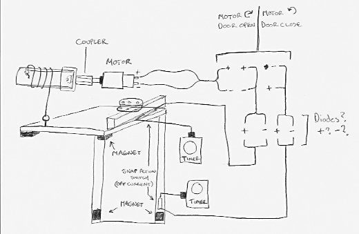
Here's a diagram of my door plan.

Maybe it will help understand the issue I am having on the wiring.
17610_autodoor1.jpg


The snap action switches are what turn off the current to the motor. The timer associated with the action (open or close) allows the current through at the selected time, then will switch off at the next hour or half hour increment. The action switches cut off the power to the motor (preventing over work and burning out) before the timer is switched off.
 
Last edited:
i can't help you with your diodes, but i can share a diode story

i had a diode lay my van up for like 3 months
sad.png


there was this intermittent problem that seemed to have a pattern, certain driving situations caused it, but it was intermittent, one day it got too bad and permanent. i had it towed home and just rode my bike to work for the rest of the summer. i got out one day determined to fix it and after wiggling every wire and vacuum hose i just happened to suck on a vacuum hose and as i set it down the engine went smooth. that didn't make sense but i did it again and same thing happened, then i just moved the hose and it did it. across the hose lay a wire with a diode on it and the diode had just gone bad.

3 months of no van, a tow, and about a year of aggravation all due to a bad diode worth cents.
roll.png
 
Dave, magnets could be used to slow the door down. I built a model of the amusement park ride called the "Drop Zone" where I used magnets opposing a copper strip to slow the vertical falling cart near the end of the fall.
 

New posts New threads Active threads

Back
Top Bottom