Automatic Chicken Coop Door - Auto Closes Coop - Beta Version 1.0

Quote:
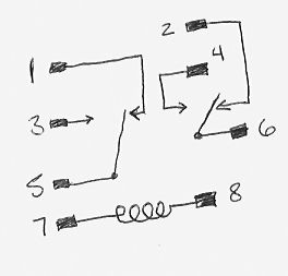
I wired the DPDT relay as follows:

1 was connected to 3
2 was connected to 4
1 and 2 were also wired out to power source and timer 1.
5 and 6 are wired out to motor.
7 and 8 are wired out to power source and timer 2.

Timer 1 controls the flow of current to motor.
Timer 2 controls the opening and closing of the relay coil, which controls the polarity of the current to the motor. So, lets say if timer 2 turns on at 4am on Wednesday, and timer 1 turns on at 5am, the door will open. If timer 2 turns off at 6am, and stays off until 4am Thursday morning, when timer 1 turns on again at 7pm Wednesday, the door will close.

As I write this out, I am afraid I haven't thought out the jobs of the switches carefully enough after the new wiring for the relay. I will have to think about this tonight to see if something has to be changed in order for the motor to stop once the door has been closed or opened.
 
Dave, great work man!

Thanks for posting the pics and for hosting them on BYC (nothing I hate worse than seeing great pics disappear from the forum when someones photobucket account goes down).

Good luck with the wiring! Once you get it all worked out please post a video of it in motion (email it to me if you want me to post it on youtube with my video).

I'm excited for ya!

thumbsup.gif
 
That's fantastic!
I'm going to "borrow" your PVC end cap idea. I was wondering what to use as a spool, but I never thought of that and I have a bunch of PVC odds&ends lying around.

At this point I am pretty settled on a vertical sliding door on the inside. We get a lot of snow and ice (starting any time now...) and I don't trust the outer hinged door to seal properly in my environment.

I also have two designs in mind:
a) the "high-tech" one that will open and close the motorized door on a timer and shut off the motor when the limit switch is hit. I have everything I need to do this except time :-(
-and-
b) the "get it working now" version that relies on me to open the door in the morning and at night a solenoid will release a latch that closes it (door will drop closed under its own weight). This I should be able to get done this weekend.
 
Quote:
Good point about the ice. Now that I think about it, I could see how ice could gum up the line on the spool as well. Maybe putting Vaseline on it would help. I am not sure if I will have to worry about that here. But its something to look out for.

I am still trying to get my mind around how the shut off switches will work with the timers. If the switch cuts the current to the motor when the door is open or closed, then the motor will be unable to move the door off the switch.

Hmm.
 
Quote:
I don't know how comfortable you are with schematic diagrams, Dave, but that's what I was trying to show in this drawing:

https://www.backyardchickens.com/forum/viewtopic.php?pid=1197431#p1197431

Sorry, I forgot I wasn't on my usual electronics forums so automatically dropped into "engineer mode" :)

In your case since you're using a single DPDT (double-pole double throw) relay to do switch the motor, you would have to put the switches in line with the relay terminal for the appropriate direction. Think of it this way: each switch has two terminals that give a normally ON condition when the lever is not pressed, so current will flow. The switch that the door will hit in the UP position must be connected in line with one of the relay terminals that drive the door UP, likewise for the DOWN switch. That way the door will move in the direction you want and when it bumps the switch lever the switch will shut off the current, but only for that direction. It can still move in the other direction.

I hope I explained that OK. You're basically building a version of a garage door opener.

Yea, I pretty much can't make sense of your schematic. Too many lines and abbreviations.
If you can explain to me how to put these switches in line with the relay, that would be great. I am pretty much stuck on this point.
 
OK, if we refer to the relay drawing you showed before(https://www.backyardchickens.com/forum/uploads/17610_relay1.jpg), this is how I would do it. I am assuming that you still are using 2 power supplies (wall warts?) and the timers switch each power supply on and off. The switch should have 3 terminals, you want to use the NC (normally closed) ones so that with the door not touching it, the switch is ON

The numbers are the ones shown on your diagram

Relay 5&6 - connect directly to motor terminals

For direction 1:
switch #1, terminal 1 -> power1 positive
switch#1, terminal 2 -> relay 1
power1 negative -> relay 2

The above will run the motor in one direction when power is applied, and it will stop when the door hits the switch.

For direction 2:
switch#2, terminal 1 ->power2 positive
switch #2, terminal 2-> relay 3
power2 negative -> relay 4
AND
power 2 positive&negative to relay 7&8

How does this work:
Say you have one timer set to turn on at 6:00 am and off at 6:30am
and the other one on at 5:00pm and off at 5:30pm so the door opens at 6 and closes at 5. Each timer controls one power supply.

At 6am the relay terminals are in the Normally Closed position and power supply #1 comes on and the motor lifts the door until the door hits switch #1, at which point the switch opens and cuts power to the motor. Then the timer shuts off at 6:30, but has no effect since the motor power is already cut.

Next, at 5:00pm, power supply #2 starts up and applies power to terminals3&4 (Normally Open) and simultaneously switches the relay over to those terminals, the motor now moves in the opposite direction (down) and runs until the door hits switch #2, and turns power off.


HOpe that explains it a bit better

--lyndon
 
If you used one power supply or a battery to run the motor an used the the relay to control it just like your doing why couldn't you power the relay with a solar battery charger. The normal position being closed, when the sun is up the door opens, sun down the door closes. Also if you wire a compacator or small battery to the solar charger too, wouldn't it charge the battery/compacator before it opens the door and discharge it before it would close the door cousing a delay at both ends. Would that work?
 
Hmmm. That would work. There may be some problem with the relay being on all the time (some relays don't like that), and it does burn a little more power, but it will work. Good idea.

As far as your idea about open at light, close at darkness. I experimented with this for a while and the problem is getting it to be repeatable enough -- most light sensors don't behave exactly how the human eye does. If it isn't done quite right, you can end up closing the door before the chickens go inside. I concluded that doing it on a timer was a safer bet.


Quote:
Why do you need 2 timers? The way you explaned the wireing why not just have power suply #1 on 24/7 an set the timer on suply #2 to come on at 5 pm an cut off at 6 am?
 

New posts New threads Active threads

Back
Top Bottom