Once again, I am upgrading my incubator. I ran into an issue with the small table-top cooler that was probably caused at least partially by my inability to quit tinkering. Hatch rates started falling and I noticed that embryo development was uneven. Moving thermometers around revealed large hot and cold spots. Lowering the wattage did little to remedy that. I think the airflow caused by the slot I cut was too drafty even when packed with padding and taped over, and the shelf didn't help either. The bottom is warped, which causes eggs to roll around if placed there when the shelf is removed. I would also like more space to set more eggs at once.
Linked below are some articles and videos that may be helpful.
Rush Lane Poultry's Video Series
Part 1 / Part 2 / Part 3 / Part 4
This video series is almost solely what I used to come up with the plans for my first build. The wiring schematics and the element locations are based directly off of this video. I highly recommend watching it if you are building a tabletop incubator of a similar shape. On the off chance that the videos have been deleted in the future, I will still include diagrams for wiring in this article.
Building the BinBator
This was my first, cheapest incubator build and the incubator that directly preceded this one. Most of the supplies for this build have been re-used from the original BinBator.
BinBator Mark Two
After several issues with the original build that I will delineate later on, I decided to create a second iteration using mostly the same parts and a different body. This article covers the construction and operation of that build.
MiniBator
These large tabletop models can be excessive for hatching only a few eggs. I built this incubator with that in mind.
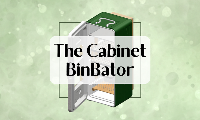
DIY Cabinet Incubator
This thread is what I based this incubator off of. It may seem overwhelming at first, but if you pay attention and break down the wiring and installation into discrete pieces it will seem more manageable. Building an incubator is not difficult!
Tools
Supplies
Measurements for the Cooler
First I cut out a hole for the two computer fans, about 9.5" in width for my specific models. (Your fans should not be too large, as the vent you will build around them is spaced about 12" outer edge to outer edge). I faced these to blow out the back, where the vent was going to be placed. They are pressure fit in there, I have no glue holding them down. I used a utility knife for this, but a jigsaw and then a utility knife to fit it more precisely may be less effort.

Image of the computer fan from inside the incubator. The fan wires were run out the vent hole that was naturally located there in the original cooler.

Next I installed the light sockets about halfway between the door and the fans, spaced evenly apart. I screwed these into the ceiling on top of two holes that I ran the wires through. As you can also see in the image, I cut the central panels out for a window measuring 11" x 7". I later cut out another identical window another third of the way down. I used a box cutter, but again, a jigsaw would be easier. At the bottom of the cooler, I cut a vent hole approximately 7.5" x 1" and located centrally about an inch up from the floor of the incubator.

Next I installed the 2 x 4s on the back and on the bottom. These were cut to be 35" in length and were spaced 12" apart OUTER edge to outer edge. Inside measurement was roughly 9.5" apart; the width of the fans. Make sure these supports extend down slightly beyond the edge of the lower air vent.

Next I attached a 12" x 41" piece of styroboard insulation and an analogously sized piece of 1/4" plywood to the back by screwing it into the 2 x 4s.


I put caps of the same material—styroboard and plywood—on the top and bottom, also screwed into place.


To prevent heat from escaping via the edges, I caulked all around the edge of the seams.
Next, I wired the STC-1000 into the fan bulbs and the extension cord I used as a wall plug. Wiring varies for different thermostats—find diagrams for whichever you decide to use. Below is the diagram for the STC-1000, wired with the cooling circuit disregarded. The side of the extension cord with the wide plug is the ground or neutral side. The smaller one indicates the hot wire.


STC-1000 probe run into the side via vent holes (3/16") drilled on each side for air ventilation.

Visual of the interior with functioning lights, fan, and probe placement.
The black adapter is the fan plug, running into another (removable) extension cord making it so that this whole build operates off one plug. You can see the screws I used to hold the extension cord block up.
Windows were completed by cutting plexiglass to 12" x 8" approximately and using hot glue to attach. Duct tape around the edges was then used for a clean, seamless look. Above you can see the thermostat installed so as to be stable, via a piece of wood screwed with short screws into the top of the incubator and then a small strip of duct tape screwed in, holding it down snugly.

The first rack below the lights has to be some type of heat baffle. I used acrylic cutting boards cut into an 11' x 16.3" square with a 6/16" taper to a 15.5" measurement. I cut this by securing it in a vice and then using a small hand saw for the majority, then a plane to make the cutting board fit snugly. The trays below the baffle are C & C cubing secured into the exact same size measurements via snug zipties.

The lower baffle you can see installed here should be the same measurements as the upper baffle, except shortened to 8.25" instead of 11". It should be placed with the lip immediately above the vent hole. I chose to support it with small boards screwed into the side for removability; hot glue may also work. A cutting board is being used in this image, but its R value—insulative quality—was too high, and I had cold spots at the bottom of the incubator, so I replaced it with the same 1/4" plywood I made the back out of. This works well.

Better image of the first baffle as well as light placements.

Tray spacings.

2021 Update
After using this incubator for a season, I can say I am quite satisfied with it. Capacity is high, temperature is even, and hatch rates are decent, though lowered due to the fact I hatch almost solely shipped eggs or eggs from fragile bloodlines. My one issue is that the temperature circulation is poor when I put in enough water pans to lockdown, hence, I would recommend the use of this incubator in conjunction with a separate lockdown incubator.
Linked below are some articles and videos that may be helpful.
Rush Lane Poultry's Video Series
Part 1 / Part 2 / Part 3 / Part 4
This video series is almost solely what I used to come up with the plans for my first build. The wiring schematics and the element locations are based directly off of this video. I highly recommend watching it if you are building a tabletop incubator of a similar shape. On the off chance that the videos have been deleted in the future, I will still include diagrams for wiring in this article.
Building the BinBator
This was my first, cheapest incubator build and the incubator that directly preceded this one. Most of the supplies for this build have been re-used from the original BinBator.
BinBator Mark Two
After several issues with the original build that I will delineate later on, I decided to create a second iteration using mostly the same parts and a different body. This article covers the construction and operation of that build.
MiniBator
These large tabletop models can be excessive for hatching only a few eggs. I built this incubator with that in mind.
DIY Cabinet Incubator
This thread is what I based this incubator off of. It may seem overwhelming at first, but if you pay attention and break down the wiring and installation into discrete pieces it will seem more manageable. Building an incubator is not difficult!
Tools
- Jigsaw
- Utility knife
- Mitre saw
- Drill
- 3/16" bit
- Impact driver
- Wire strippers
Supplies
- Any 150 litre cooler such as this one
- Two 60+ CFM computer/gaming fans
- 12v AC/DC adapter
- Two light sockets
- Two light bulbs—25 to 60 watts (I used 40w)
- A digital thermostat such as the STC-1000
- One cutting board (11" x 16" or bigger)
- Quarter inch plywood
- One two by four
- Styroboard insulation
- Caulk
- Plexiglass for windows
- Hot glue / liquid nails / gasket sealer
- Duct tape
- 2.5" screws
- Extension cord
- Assorted wire nuts
Measurements for the Cooler
- Outside: 42" x 18" x 16"
- Inside: 38.5" x 16.3" x 15"
- Inner door width: 12.5"
First I cut out a hole for the two computer fans, about 9.5" in width for my specific models. (Your fans should not be too large, as the vent you will build around them is spaced about 12" outer edge to outer edge). I faced these to blow out the back, where the vent was going to be placed. They are pressure fit in there, I have no glue holding them down. I used a utility knife for this, but a jigsaw and then a utility knife to fit it more precisely may be less effort.
Image of the computer fan from inside the incubator. The fan wires were run out the vent hole that was naturally located there in the original cooler.
Next I installed the light sockets about halfway between the door and the fans, spaced evenly apart. I screwed these into the ceiling on top of two holes that I ran the wires through. As you can also see in the image, I cut the central panels out for a window measuring 11" x 7". I later cut out another identical window another third of the way down. I used a box cutter, but again, a jigsaw would be easier. At the bottom of the cooler, I cut a vent hole approximately 7.5" x 1" and located centrally about an inch up from the floor of the incubator.
Next I installed the 2 x 4s on the back and on the bottom. These were cut to be 35" in length and were spaced 12" apart OUTER edge to outer edge. Inside measurement was roughly 9.5" apart; the width of the fans. Make sure these supports extend down slightly beyond the edge of the lower air vent.
Next I attached a 12" x 41" piece of styroboard insulation and an analogously sized piece of 1/4" plywood to the back by screwing it into the 2 x 4s.
I put caps of the same material—styroboard and plywood—on the top and bottom, also screwed into place.
To prevent heat from escaping via the edges, I caulked all around the edge of the seams.
Next, I wired the STC-1000 into the fan bulbs and the extension cord I used as a wall plug. Wiring varies for different thermostats—find diagrams for whichever you decide to use. Below is the diagram for the STC-1000, wired with the cooling circuit disregarded. The side of the extension cord with the wide plug is the ground or neutral side. The smaller one indicates the hot wire.
STC-1000 probe run into the side via vent holes (3/16") drilled on each side for air ventilation.
Visual of the interior with functioning lights, fan, and probe placement.
The black adapter is the fan plug, running into another (removable) extension cord making it so that this whole build operates off one plug. You can see the screws I used to hold the extension cord block up.
Windows were completed by cutting plexiglass to 12" x 8" approximately and using hot glue to attach. Duct tape around the edges was then used for a clean, seamless look. Above you can see the thermostat installed so as to be stable, via a piece of wood screwed with short screws into the top of the incubator and then a small strip of duct tape screwed in, holding it down snugly.
The first rack below the lights has to be some type of heat baffle. I used acrylic cutting boards cut into an 11' x 16.3" square with a 6/16" taper to a 15.5" measurement. I cut this by securing it in a vice and then using a small hand saw for the majority, then a plane to make the cutting board fit snugly. The trays below the baffle are C & C cubing secured into the exact same size measurements via snug zipties.
The lower baffle you can see installed here should be the same measurements as the upper baffle, except shortened to 8.25" instead of 11". It should be placed with the lip immediately above the vent hole. I chose to support it with small boards screwed into the side for removability; hot glue may also work. A cutting board is being used in this image, but its R value—insulative quality—was too high, and I had cold spots at the bottom of the incubator, so I replaced it with the same 1/4" plywood I made the back out of. This works well.
Better image of the first baffle as well as light placements.
Tray spacings.
2021 Update
After using this incubator for a season, I can say I am quite satisfied with it. Capacity is high, temperature is even, and hatch rates are decent, though lowered due to the fact I hatch almost solely shipped eggs or eggs from fragile bloodlines. My one issue is that the temperature circulation is poor when I put in enough water pans to lockdown, hence, I would recommend the use of this incubator in conjunction with a separate lockdown incubator.


") i really liked it!
i really liked it!