- Oct 9, 2010
- 449
- 13
- 111
Many people use incandescent light bulbs as their incubator's heating elements, but I really think resistance wire is better and I was wondering if anyone has already tried it before (in home made incubators off course)?
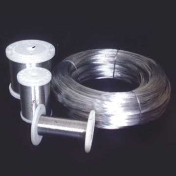
All commercial incubators use resistance wire. In the next picture do you see the rounded square on the top part? Is resistance wire.

Resistance wire is a low resistance conductor, classified by Ohms/feet (Ohm is the unit for electrical resistance), that heats up when crossed by an electric current, it is usually used for high temperature applications but if properly chosen and controlled it can have several advantages over light bulbs. (Do not produces light, do not wreck suddenly creating a risk of loosing all the eggs, reacts very fast to applied voltage, last for a life in you incubator and more that I don't remember now)
Disadvantages only can think about the price which is higher than a regular light bulb.
Now the trick part, choose the correct wire,
I know I need between 200 and 500W for my incubator,
P = [200,500] watts
And my power supply is 220 Vac,
V = 220 Vac
Electric power formula (derivation from Ohm's law),
P=VI <=> I=P/V
I=[200,500]/220=[200/220,500/220] A (amperes)
Ohm's Law,
V=RI <=> R=V/I
R=220/[200/220,500/220] = [220^2/500, 220^2/200] = [96.8, 242] Ohm
Now you have the resistance your wire should have between 96.8Ohm and 242Ohm to produce between 200W and 500W under 220Vac applied voltage. So if you find a wire for sale that have 50Ohm/feet, you need to buy approximately between 2 feet=100Ohm and 5 feet=250Ohm.
For last but not least, you should check you wire Max Watt per feet value to know if it can handle the power you are going to put in.
Example:
The 50Ohm/feet wire we found on the shop can handle up to 150W per feet, so if I'm going to buy 2 feet the wire will be able to handle 300W which is less than the power you you are going to want, 200W, so its safe to apply 220V at this 2 feet of wire getting 200W of heat for my incubator!
Hope you all understood it, any questions/corrections please post bellow.


