chicken-dad
In the Brooder
- Dec 15, 2020
- 2
- 0
- 12
I constructed my coop in early fall, excited to house four new 28-week old red sex-linked chickens. However, with the coldest nights of the Maine winter soon approaching, I began to worry that the henhouse wouldn't be warm enough for them. I could have gone the easy route, and purchased a portable thermometer (and I did… eventually) but instead, I decided to put my newly learned transport engineering skills to work to create a thermal model usable by any backyard farmers hoping to design and build their own coop!
I have included my step by step process below, as well as explanations to some of the mathematics involved. The plans I used are linked below, but with a little research of your materials, you can apply this model to any simply built coop you may have plans for. If you are only interested in the results of the study, they can be found bolded at the bottom of the thread.

My coop, in early fall
My roommates and I constructed the coop using these plans, with slight modification to the door in the side panel. The top portion of the a-frame at the back of the coop is a wall with an egg collection door, not pictured above.
The chickens sleep each night in the upper level of the a-frame, a triangular prism-shaped section of the coop made with ½ in plywood with one open face to allow the chickens to come and go as they please.
The chickens’ sleeping quarters, faces of the "room" labeled A-D
The floor (D) is coated with ¾ in of wood shavings, and on the colder nights, a 0.39 in thick (I measured) mineral-fiber moving blanket is draped across the top of the coop such that it covers faces A, B, and C. To simplify this model, I assumed that any small gaps in the construction, the frame itself, and any wind velocity were negligible.
The first thing I had to do was find out where that heat was coming from in my system, and where it was going. Within my coop’s sleeping area is a radiation heater which outputs 50W of heat. However, the chickens also generate approximately 10W of heat each, meaning I will have to account for the heat generated by both the heater and the four chickens.
The next thing to do was to map out the total thermal resistance of the sleeping area: this is a measurement of how much the system will resist heat transfer. To start, I created a thermal resistance network, mapping out the different ways heat can escape from the system.
As the heater is radiation-based and directed at the bedding, I assumed the heat within the network is "starting" at the top surface of the bedding (with minimal heat lost in radiation), and set that as the start of my path. Additionally, I assumed that, due to their natural insulation from the air around them, the dominant part of heat lost by the chickens is lost through their contact with the bedding as they sleep. The paths all “end” when the heat reaches the outside air, and is fully “lost”. Each time the heat has to pass from one material to another, a "thermal resistance" is drawn, represented by the zigzags symbol for a resistor. I was able to map out the thermal resistances as seen below, labeling each boundary at the points of connection between resistances.
Thermal Resistance Network of the sleeping area
In this model, I dealt with two types of thermal resistance: resistance to conduction (heat moving through a body) and resistance to convection (heat being carried away from or to a body by a warmed fluid). Thermal resistance to conduction can be calculated using the equation

where L is the thickness of the object heat is passing through, k is the thermal conductivity of the object (a material property that describes ability to conduct heat), and A is the area of the face heat is trying to pass through. Thermal resistance to convection can be calculated by the equation

where h is the convective heat transfer coefficient (an experimentally determined value that describes the convection process in a certain situation) and A is the area of the face heat is trying to pass through.
The next step was to find all of the relevant values of k, h, and L for the materials I used. If you are creating your own thermal model, you would substitute your values where I have included mine below. This is a good place to look for k values. As h values are experimentally determined, you can try using the values I used, and see if your end result makes sense. If not, try researching to find if someone has modeled a situation that better fits your circumstances.

Having found these values, I then went about calculating all of the different individual thermal resistances. Any resistance that represents “passing through” an object, like R(1) represents heat passing through the bedding on its way to the floor, is conduction resistance, and is calculated as follow:

Plug in the thickness of the material for L (in meters), the area of the surface for A (in m^2), and the thermal conductivity value for k (in W/m-k) like so:

If you are following along, check your units. You should end up with Kelvin/Watt.
Any resistance that represents warmed fluid (air, in this case) moving away from or towards object, like R(3) represents warmed air floating away from the bedding, is convection resistance, and is calculated as follow:

Plug in the convective heat transfer coefficient value for h (in W/m^2-k), and the area of the surface for A (in m^2).

Check your units again, you should still end up with Kelvin/Watt.
For my model, my resistance values were as follows:

From there, it was a matter of calculating the total heat resistance of the network. Total thermal resistance is calculated the same way that total electrical resistance is calculated, with resistances in series adding to

and resistances in parallel adding to

with the principles stacking for each individual “branch” of a network. Take, for example, the resistance network below.
Example Resistance Network
It would have the following total resistance between A and D of:

For the thermal resistance network modeling my network (see Page 3), the total thermal resistance can expressed as:

Plugging in the values I got for the different thermal resistances, I calculated my total thermal resistance.

Check units, you should still have a value in Kelvin/Watt.
Now, we can finally calculate the amount of heat in degrees Kelvin that the sleeping area retains for the chickens. Using the equation

where Q is the heat flowing out of a network, T(in) is the temperature at the start of the resistance network (in this case, the temperature of the bedding), T(out) is the temperature of the end of the resistance network (here, the temperature of the outside air), and R(tot) is the total resistance of the network.
Calculating Q is easy; as the system has its own internal source of heat, we can assume that the sleeping area is a steady system, meaning that once it reaches its equilibrium temperature, Q(in)=Q(out). (Here we focus on the system when it has reached its equilibrium temperature after the sun has set and the outside air has cooled, as we only care about the temperature of the sleeping area at night.) As the sleeping area uses a 50W heater and, according to my research, chickens put off approximately 10W of heat each, the amount of heat per unit time coming out of my system is

Plugging the values of Q and R(tot) into the equation stated below, I derived

where ΔT is how much warmer the sleeping area is than the outside air. This means my coop’s sleeping area keeps the bedding 16.8 degrees warmer (in F) than the outside air.
Given that where I live (Cornish, Maine) sees on average lowest nightly temperatures of 12-24 degrees F, the sleeping area’s lowest nightly temperature ranges from 28.8 to 40.8 degrees. As my chickens are able to survive temperatures reaching the mid-teens, my coop holds a sufficient amount of heat to keep them healthy. Be sure to check what temperatures your chickens are most comfortable with before acting on the results of any models you make, as well as consider the many other needs of a chicken in the wintertime.
To validate these numbers I purchased two bluetooth thermometers (and yes, I realize I could have done this from the beginning, but that wasn’t the point), and measured the temperatures of both the outside air and sleeping area bedding overnight. Sure enough, I found that, while the outside air temperature dropped to an average minimum of 19.4 °F, the bedding of the chicken coop only reached 33 °F, meaning an experimental average temperature difference of 13.6 °F. The reasons for the difference in retained heat likely lie in the small gaps in the sleeping area’s construction where doors meet with door frames, as well as the presence of wind increasing the convective heat transfer coefficient of the outside surface.
I hope that I have helped you in the process modeling the the warmth of your coop! While it is much less mathematically complex to buy a thermometer to begin with, this method will hopefully be useful to those of you who have not yet designed your coop, or are deciding what you’ll need to buy. Please feel free to comment any questions you have. When it comes to backyard farming, everyone knows that experience and wisdom are king... But a little thermodynamic engineering never hurt anyone!
I have included my step by step process below, as well as explanations to some of the mathematics involved. The plans I used are linked below, but with a little research of your materials, you can apply this model to any simply built coop you may have plans for. If you are only interested in the results of the study, they can be found bolded at the bottom of the thread.
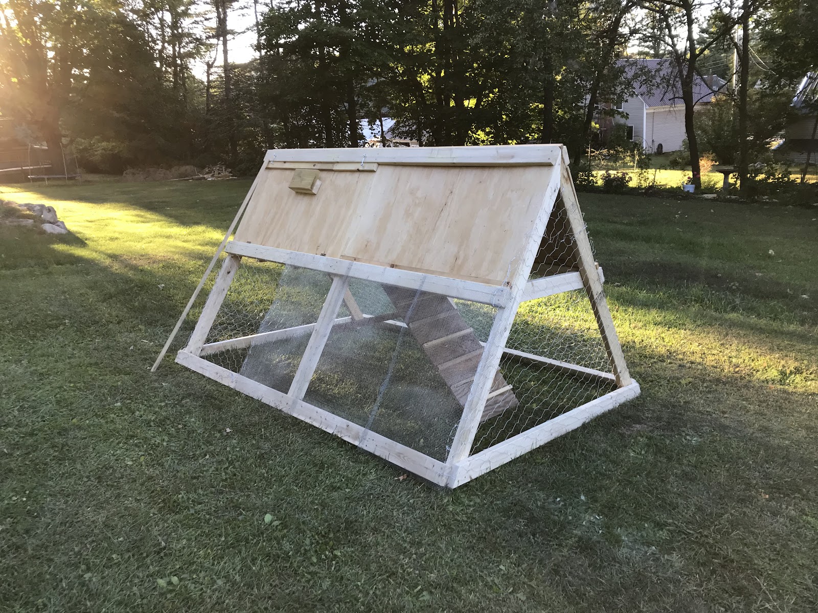
My coop, in early fall
My roommates and I constructed the coop using these plans, with slight modification to the door in the side panel. The top portion of the a-frame at the back of the coop is a wall with an egg collection door, not pictured above.
The chickens sleep each night in the upper level of the a-frame, a triangular prism-shaped section of the coop made with ½ in plywood with one open face to allow the chickens to come and go as they please.
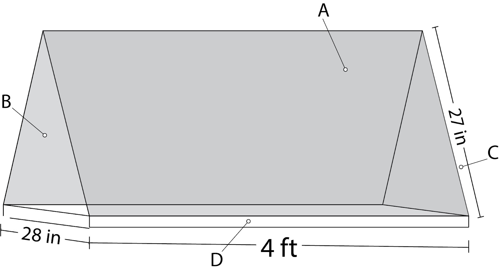
The chickens’ sleeping quarters, faces of the "room" labeled A-D
The floor (D) is coated with ¾ in of wood shavings, and on the colder nights, a 0.39 in thick (I measured) mineral-fiber moving blanket is draped across the top of the coop such that it covers faces A, B, and C. To simplify this model, I assumed that any small gaps in the construction, the frame itself, and any wind velocity were negligible.
The first thing I had to do was find out where that heat was coming from in my system, and where it was going. Within my coop’s sleeping area is a radiation heater which outputs 50W of heat. However, the chickens also generate approximately 10W of heat each, meaning I will have to account for the heat generated by both the heater and the four chickens.
The next thing to do was to map out the total thermal resistance of the sleeping area: this is a measurement of how much the system will resist heat transfer. To start, I created a thermal resistance network, mapping out the different ways heat can escape from the system.
As the heater is radiation-based and directed at the bedding, I assumed the heat within the network is "starting" at the top surface of the bedding (with minimal heat lost in radiation), and set that as the start of my path. Additionally, I assumed that, due to their natural insulation from the air around them, the dominant part of heat lost by the chickens is lost through their contact with the bedding as they sleep. The paths all “end” when the heat reaches the outside air, and is fully “lost”. Each time the heat has to pass from one material to another, a "thermal resistance" is drawn, represented by the zigzags symbol for a resistor. I was able to map out the thermal resistances as seen below, labeling each boundary at the points of connection between resistances.
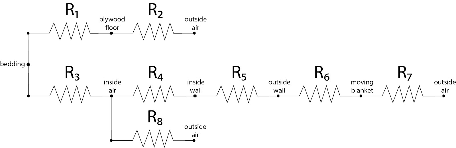
Thermal Resistance Network of the sleeping area
In this model, I dealt with two types of thermal resistance: resistance to conduction (heat moving through a body) and resistance to convection (heat being carried away from or to a body by a warmed fluid). Thermal resistance to conduction can be calculated using the equation
where L is the thickness of the object heat is passing through, k is the thermal conductivity of the object (a material property that describes ability to conduct heat), and A is the area of the face heat is trying to pass through. Thermal resistance to convection can be calculated by the equation
where h is the convective heat transfer coefficient (an experimentally determined value that describes the convection process in a certain situation) and A is the area of the face heat is trying to pass through.
The next step was to find all of the relevant values of k, h, and L for the materials I used. If you are creating your own thermal model, you would substitute your values where I have included mine below. This is a good place to look for k values. As h values are experimentally determined, you can try using the values I used, and see if your end result makes sense. If not, try researching to find if someone has modeled a situation that better fits your circumstances.
Having found these values, I then went about calculating all of the different individual thermal resistances. Any resistance that represents “passing through” an object, like R(1) represents heat passing through the bedding on its way to the floor, is conduction resistance, and is calculated as follow:
Plug in the thickness of the material for L (in meters), the area of the surface for A (in m^2), and the thermal conductivity value for k (in W/m-k) like so:
If you are following along, check your units. You should end up with Kelvin/Watt.
Any resistance that represents warmed fluid (air, in this case) moving away from or towards object, like R(3) represents warmed air floating away from the bedding, is convection resistance, and is calculated as follow:
Plug in the convective heat transfer coefficient value for h (in W/m^2-k), and the area of the surface for A (in m^2).
Check your units again, you should still end up with Kelvin/Watt.
For my model, my resistance values were as follows:
and resistances in parallel adding to
with the principles stacking for each individual “branch” of a network. Take, for example, the resistance network below.
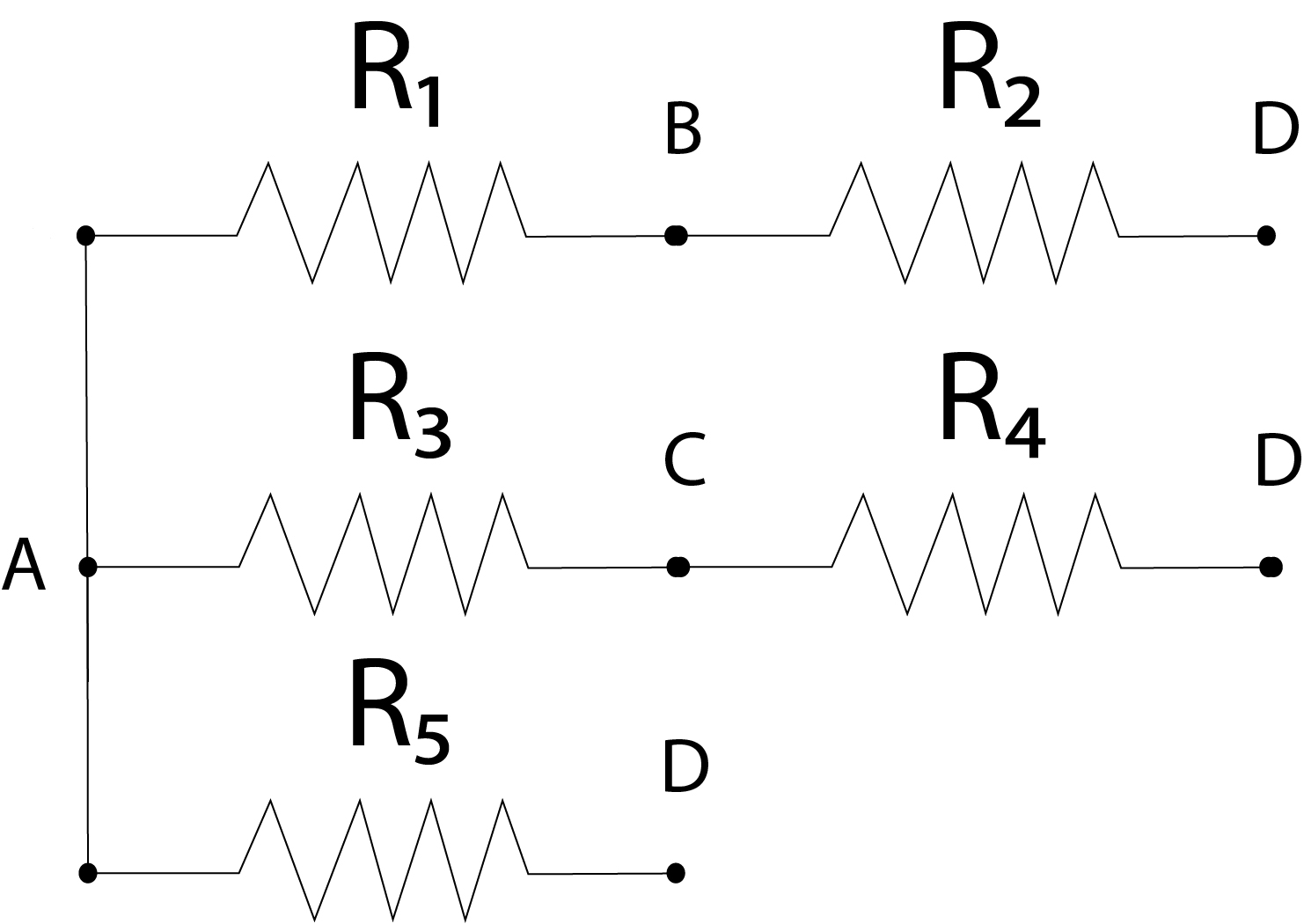
Example Resistance Network
It would have the following total resistance between A and D of:
For the thermal resistance network modeling my network (see Page 3), the total thermal resistance can expressed as:
Plugging in the values I got for the different thermal resistances, I calculated my total thermal resistance.
Check units, you should still have a value in Kelvin/Watt.
Now, we can finally calculate the amount of heat in degrees Kelvin that the sleeping area retains for the chickens. Using the equation
where Q is the heat flowing out of a network, T(in) is the temperature at the start of the resistance network (in this case, the temperature of the bedding), T(out) is the temperature of the end of the resistance network (here, the temperature of the outside air), and R(tot) is the total resistance of the network.
Calculating Q is easy; as the system has its own internal source of heat, we can assume that the sleeping area is a steady system, meaning that once it reaches its equilibrium temperature, Q(in)=Q(out). (Here we focus on the system when it has reached its equilibrium temperature after the sun has set and the outside air has cooled, as we only care about the temperature of the sleeping area at night.) As the sleeping area uses a 50W heater and, according to my research, chickens put off approximately 10W of heat each, the amount of heat per unit time coming out of my system is
Plugging the values of Q and R(tot) into the equation stated below, I derived
where ΔT is how much warmer the sleeping area is than the outside air. This means my coop’s sleeping area keeps the bedding 16.8 degrees warmer (in F) than the outside air.
Given that where I live (Cornish, Maine) sees on average lowest nightly temperatures of 12-24 degrees F, the sleeping area’s lowest nightly temperature ranges from 28.8 to 40.8 degrees. As my chickens are able to survive temperatures reaching the mid-teens, my coop holds a sufficient amount of heat to keep them healthy. Be sure to check what temperatures your chickens are most comfortable with before acting on the results of any models you make, as well as consider the many other needs of a chicken in the wintertime.
To validate these numbers I purchased two bluetooth thermometers (and yes, I realize I could have done this from the beginning, but that wasn’t the point), and measured the temperatures of both the outside air and sleeping area bedding overnight. Sure enough, I found that, while the outside air temperature dropped to an average minimum of 19.4 °F, the bedding of the chicken coop only reached 33 °F, meaning an experimental average temperature difference of 13.6 °F. The reasons for the difference in retained heat likely lie in the small gaps in the sleeping area’s construction where doors meet with door frames, as well as the presence of wind increasing the convective heat transfer coefficient of the outside surface.
I hope that I have helped you in the process modeling the the warmth of your coop! While it is much less mathematically complex to buy a thermometer to begin with, this method will hopefully be useful to those of you who have not yet designed your coop, or are deciding what you’ll need to buy. Please feel free to comment any questions you have. When it comes to backyard farming, everyone knows that experience and wisdom are king... But a little thermodynamic engineering never hurt anyone!


