DIY : Automatic Chicken Coop Door With Timer & Solar Charger

I put together a little video showing how you can make an automatic chicken door with a power car antenna and a timer in hopes it inspires you to add one to your coop!


If you found the video helpful, please give it a "Thumbs Up" on Youtube.
Thanks for watching!

Here's a pictorial describing the process:
DSCN2022.JPG


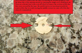
Start with a power car antenna
20170731_172711.jpg


cover off.jpg


2nd position.jpg


tabs away.jpg


tape disc.jpg


disc3.jpg


mount.jpg


Attach the car antenna to the wall of your coop
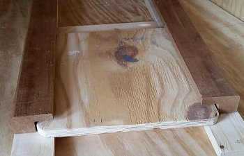
20170803_115751.jpg


Build a door guide
20170803_113503.jpg


door1.jpg


door weight.jpg


door2.jpg


Mount the timer & battery then attach the wires.
20170811_132321.jpg


wire timer.jpg


Organize the wires
20170811_133228.jpg


Now it's time to add the solar panel. Lets go!

Buy a solar panel and charge controller.
DSCN1979.JPG


Attach a longer lead to the solar panel if needed. I used an outdoor extension cord which was easily soldered to the back of the panel.
DSCN1980.JPG


Make some mounting brackets out of 1/8" thick aluminum available from your local home center.
DSCN1981.JPG


Use some stainless steel nuts and bolts to attach the brackets to the panel
DSCN1983.JPG


And to the attach the panel to the mount.
DSCN1984.JPG


Attach mount to coop with u-bolts and route wire into coop.
DSCN1989.JPG


DSCN1999.JPG


Attach charger controller and connect wires. Make sure to connect the battery first, followed by the solar panel and then the antenna (load).
DSCN1996.JPG


controller.jpg


layout1.jpg


All you have to do is set the time on the timer and then enter the times that you'd like the door to open and close. I have been using this system for a few weeks now and have had no issues. The solar panel charges the battery even on cloudy days.

Here's a list of the parts I used:
Solar Panel: http://amzn.to/2wybora
Solar Charge Controller: http://amzn.to/2xbPrBM
Power Car Antenna: http://amzn.to/2ioEJmb
Solar Panel Mount: http://amzn.to/2fbTLeg
12V Timer: http://amzn.to/2g4yinl
12V Battery: http://amzn.to/2wlWkRm
Wire Connectors: http://amzn.to/2ipEp6M

Let me know what you think. Pros? Cons?

Latest reviews

I think I'll try it!
  • Like
Reactions: Rondack
  • Like
Reactions: Rondack

Comments

A Quick Update:
It's been 2 months now and the automatic chicken coop door has been working flawlessly. The longest stretch without sunlight has been 2 days so far and the battery is large enough to still continue to work. I will add that on cloudy days the solar panel is still maintaining the battery.

If anyone else has tried this, please post your experience.
 
I have gotten it up but I only have 2 red lights. When the door is opening or closing the second light dims. It is also losing the second green light at times, then I have to disconnect the battery and start it over. Any ideas?
 
I have gotten it up but I only have 2 red lights. When the door is opening or closing the second light dims. It is also losing the second green light at times, then I have to disconnect the battery and start it over. Any ideas?
Here's what the lights mean:
"Charge" LED (Green) : When lit, it means your battery is charging. When out (like at night when no light shining on solar panel it will be unlit. When the battery is peak charged, the "Charge" LED will flicker meaning it is in a state of float charging.

"Load" LED (Green) : When lit it means there is enough power in the battery to operate a load. When unlit it means it will not send power to the load, ie. door motor.

"Battery LEDS (Red) : You need a minimum of 2 red LEDS for the load to receive power. Mine is almost always showing 2 red LEDS. On sunny days (I'm very far north) the 3rd LED will light up. If you have only 1 red battery LED showing, it means that the battery is too low on power to actuate the door.

I hope this helps. It sounds like your battery may be low. Did you use a new battery or old? Have you had sunny days? My battery lasts 7 days with no sun shining before I have to charge it up. These are completely cloudy days with rain. If I get a day of sun, it completely charges the battery.

Also make sure to connect the battery to the charge controller first, then the solar panel and finally the load (antenna).
 
I made a door similar to this but burned out 2 motors within a year, I don’t think they liked the cold. I now use a linear actuator instead. It was about $60 on Amazon, moves 12 inches and can lift 300 lbs. It seems much, much more reliable. I had to wire it using a relay because you switch the polarity to raise or lower it. I have it hooked up to a solar panel, battery, and photocell and it works flawlessly. Opens up at dawn closes when dark. I would suggest that as a motor instead of the antenna motor for the long haul but other than that this is an excellent tutorial, though different from my doors. Sorry I don't know how to make the photo smaller.
61JKh0S%2BYqL._SL1200_.jpg
I have the same setup as you but not with a photocell. Would you mind sharing how you have that set up and where you got your photocell from?
 
Good job. I just realized I have seen your video on You Tube and subscribed. I like all aspects of your project. My storage shed doesn't have power and I am considering a solar arrangement so I could run some led lights when needed, and maybe power a small security camera. The camera doesn't draw much and if needed, I could use two batteries. Your video was very helpful. Thanks for sharing.
 
I made a door similar to this but burned out 2 motors within a year, I don’t think they liked the cold. I now use a linear actuator instead. It was about $60 on Amazon, moves 12 inches and can lift 300 lbs. It seems much, much more reliable. I had to wire it using a relay because you switch the polarity to raise or lower it. I have it hooked up to a solar panel, battery, and photocell and it works flawlessly. Opens up at dawn closes when dark. I would suggest that as a motor instead of the antenna motor for the long haul but other than that this is an excellent tutorial, though different from my doors. Sorry I don't know how to make the photo smaller.
61JKh0S%2BYqL._SL1200_.jpg
The photocell is from amazon. Something similar to this for $7.
https://www.amazon.com/HIGHROCK-Pho...D=41aoJRMG%2BFL&preST=_SX300_QL70_&dpSrc=srch

I did have to do some googling and some tinkering to make it work. Basically I had to wire a DPDT relay I also got on amazon to make the polarity reverse when the photocell was activated. It sounds more complicated than it was but works really well after some tinkering.
 
I followed these instructions with minor alterations (mounting brackets and aluminum door glides instead of wood—smoother and no warping or swelling). I also bought 2 batteries as I find that on short NW cloudy, winter days the battery will eventually run down. I keep the spare on a charger in the garage.
However, after 2 years my antenna failed—internal gears stripped. No problem, I though, a new one was only $15 and I figured if I got 2 more years that was a reasonable cost. My new one arrived last week and looks identical to the original. However, when I removed the cover to expose the disc/wheel so I could grind it to customize the stop points—there was no wheel. They’ve gone solid state and there’s no way to limit the antenna’s extension or retraction points. Does anyone know a source for the “old school” antennas. As I said—you can’t go by looks—from the outside the old and new are identical in every way.
You can go to this thread, and read thru, they use a different plunger, that you may be able to use in your setup.
https://www.backyardchickens.com/threads/my-diy-automatic-chicken-door.1295391/
 
I have followed the instructions above, but I am stumped about how to connect the charge controller to the antenna. This is probably a very rudimentary question and I apologize for its simplicity, but I would greatly appreciate an explanation of picture of someone else's setup. Thanks
 
I made a door similar to this but burned out 2 motors within a year, I don’t think they liked the cold. I now use a linear actuator instead. It was about $60 on Amazon, moves 12 inches and can lift 300 lbs. It seems much, much more reliable. I had to wire it using a relay because you switch the polarity to raise or lower it. I have it hooked up to a solar panel, battery, and photocell and it works flawlessly. Opens up at dawn closes when dark. I would suggest that as a motor instead of the antenna motor for the long haul but other than that this is an excellent tutorial, though different from my doors. Sorry I don't know how to make the photo smaller.
61JKh0S%2BYqL._SL1200_.jpg
I'm looking at doing the same setup -- but I'm electrically cchanllenged. Can you post a picture / diagram of the relay switch and how you wired that? THANKS!!
 
I'm looking at doing the same setup -- but I'm electrically cchanllenged. Can you post a picture / diagram of the relay switch and how you wired that? THANKS!!

There is more than one way to skin a cat, but this would be the setup i might go with if using an actuator.
The relay terminal numbers are based on this Relay
Untitled1.png

You can use battery system or a wall wart, but you power a timer and set the time to turn on and then off. On time is door close, timer activates, energizes relay and closes door. Timer turns off in morning, relay de-energizes and polarity is reversed, door opens.

I noticed in some older threads a user made a long post concerning amperage and fire if a wire burned up. The actuator says 3A max load, a #16 wire is good to 10 amps i think, the motor would burn out before the wire. But if you are concerned you can stick in some automotive fuse cartridges on both terminals for 5 amps to be on the safe side.
 
There is more than one way to skin a cat, but this would be the setup i might go with if using an actuator.
The relay terminal numbers are based on this Relay
View attachment 2485764
You can use battery system or a wall wart, but you power a timer and set the time to turn on and then off. On time is door close, timer activates, energizes relay and closes door. Timer turns off in morning, relay de-energizes and polarity is reversed, door opens.

I noticed in some older threads a user made a long post concerning amperage and fire if a wire burned up. The actuator says 3A max load, a #16 wire is good to 10 amps i think, the motor would burn out before the wire. But if you are concerned you can stick in some automotive fuse cartridges on both terminals for 5 amps to be on the safe side.
First time chicken keeper here, first post also, sorry to bump such an old post, but I plan on following this build with the linear actuator, but no photo cell, just the timer the OP used. Below is the actuator. https://www.amazon.com/dp/B00NM8H5P...abc_FVAKPGHCJNACQ0H2EMNJ?_encoding=UTF8&psc=1
Wiring and Electric is the one skilled trades I have no experience with and I've been googling and reading through what seems like a foreign language to me. 😅 Can I do this same build and just sub the photocell for the timer and wire it like you have diagrammed above if I order that relay?
Thanks in advance!
 
May have found my answer here, I think I'll be using the switch from this video
, with the battery application and solar panel from the build in this thread. Electrically inclined people, it should work, yeah?
 
The photocell contact would replace the timer output contact above the relay coil. I would consider adding a switch so you manually open/close the actuator. The timer i uses has a button where i can do that, but its rather annoying and sometimes i forget to put it back in auto.
 
Last edited:
There is more than one way to skin a cat, but this would be the setup i might go with if using an actuator.
The relay terminal numbers are based on this Relay
View attachment 2485764
You can use battery system or a wall wart, but you power a timer and set the time to turn on and then off. On time is door close, timer activates, energizes relay and closes door. Timer turns off in morning, relay de-energizes and polarity is reversed, door opens.

I noticed in some older threads a user made a long post concerning amperage and fire if a wire burned up. The actuator says 3A max load, a #16 wire is good to 10 amps i think, the motor would burn out before the wire. But if you are concerned you can stick in some automotive fuse cartridges on both terminals for 5 amps to be on the safe side.
I trying to be rude here but I work with electronics a lot and I don't get what you are trying to do with that diagram. Yeah more than one way to skin a cat but some ways are just a huge WHY.

Also NO. 16 AWG is way too much for this sort of thing. Over gauging your wire is just over doing it for no reason. Most Linear Actuators of this type 250 lb 900n commonly used for Chicken Doors use an 18 AWG wire. Or even 20AWG. Out of the 20+ actuators I have ordered or found, there has only been ONE that used 16AWG.

Also Those actuators say 3A MAX. That is the amps that it can draw @ MAX weight or MAX effort. Meaning that 250lbs. If you are getting up that high in amps being drawn they you are way passed the time to have cut the power and the door may already be destroyed. Again the 20+ actuators I have(of this type), the most amps that they draw is 0.6 amps. Under normal operation. I have tested many and found that by the time it even gets to the 1 amp, you are already breaking things. The best thing to do is run it under normal operation (with door weight) and see what amps are being drawn. Then put it under a load like pushing back on it with your own arm strength. Then use that amperage to gauge what fuse or breaker you need.

I only use a 1 amp breaker or fuse on these type 250 lb 900n actuators.

On my homemade Linear Actuators, made with drill motors, I use a 2 AMP fuse or breaker.

Last, If at all possible use slow blow fuses for the actuator. Motors tend to draw more current at start up.
 

Article information

Author
jballone
Article read time
2 min read
Views
61,979
Comments
30
Reviews
4
Last update
Rating
3.57 star(s) 7 ratings

More from jballone

Share this article

Back
Top Bottom