DIY : Automatic Chicken Coop Door With Timer & Solar Charger

I put together a little video showing how you can make an automatic chicken door with a power car antenna and a timer in hopes it inspires you to add one to your coop!


If you found the video helpful, please give it a "Thumbs Up" on Youtube.
Thanks for watching!

Here's a pictorial describing the process:
DSCN2022.JPG


Start with a power car antenna
20170731_172711.jpg


cover off.jpg


2nd position.jpg


tabs away.jpg


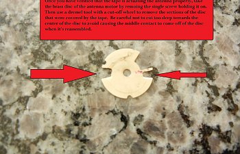
tape disc.jpg


disc3.jpg


mount.jpg


Attach the car antenna to the wall of your coop
20170803_115751.jpg


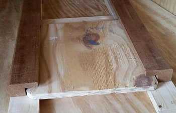
Build a door guide
20170803_113503.jpg


door1.jpg


door weight.jpg


door2.jpg


Mount the timer & battery then attach the wires.
20170811_132321.jpg


wire timer.jpg


Organize the wires
20170811_133228.jpg


Now it's time to add the solar panel. Lets go!

Buy a solar panel and charge controller.
DSCN1979.JPG


Attach a longer lead to the solar panel if needed. I used an outdoor extension cord which was easily soldered to the back of the panel.
DSCN1980.JPG


Make some mounting brackets out of 1/8" thick aluminum available from your local home center.
DSCN1981.JPG


Use some stainless steel nuts and bolts to attach the brackets to the panel
DSCN1983.JPG


And to the attach the panel to the mount.
DSCN1984.JPG


Attach mount to coop with u-bolts and route wire into coop.
DSCN1989.JPG


DSCN1999.JPG


Attach charger controller and connect wires. Make sure to connect the battery first, followed by the solar panel and then the antenna (load).
DSCN1996.JPG


controller.jpg


layout1.jpg


All you have to do is set the time on the timer and then enter the times that you'd like the door to open and close. I have been using this system for a few weeks now and have had no issues. The solar panel charges the battery even on cloudy days.

Here's a list of the parts I used:
Solar Panel: http://amzn.to/2wybora
Solar Charge Controller: http://amzn.to/2xbPrBM
Power Car Antenna: http://amzn.to/2ioEJmb
Solar Panel Mount: http://amzn.to/2fbTLeg
12V Timer: http://amzn.to/2g4yinl
12V Battery: http://amzn.to/2wlWkRm
Wire Connectors: http://amzn.to/2ipEp6M

Let me know what you think. Pros? Cons?

Latest reviews

I think I'll try it!
  • Like
Reactions: Rondack
  • Like
Reactions: Rondack

Comments

I followed these instructions with minor alterations (mounting brackets and aluminum door glides instead of wood—smoother and no warping or swelling). I also bought 2 batteries as I find that on short NW cloudy, winter days the battery will eventually run down. I keep the spare on a charger in the garage.
However, after 2 years my antenna failed—internal gears stripped. No problem, I though, a new one was only $15 and I figured if I got 2 more years that was a reasonable cost. My new one arrived last week and looks identical to the original. However, when I removed the cover to expose the disc/wheel so I could grind it to customize the stop points—there was no wheel. They’ve gone solid state and there’s no way to limit the antenna’s extension or retraction points. Does anyone know a source for the “old school” antennas. As I said—you can’t go by looks—from the outside the old and new are identical in every way.
Add a limit switch with diode.
 
The photocell contact would replace the timer output contact above the relay coil. I would consider adding a switch so you manually open/close the actuator. The timer i uses has a button where i can do that, but its rather annoying and sometimes i forget to put it back in auto.
I am interested in seeing the way and where you would add a manual override switch, to this, that won't compromise the system?

As far as forgetting to put back from manual (I know you were talking about the internal "manual" operation switch in the timer but) , have you given any thought to using a Mechanical Spring Timer switch? The first one is for up to 15 min and the this one is for up to an hour.
 
Disclaimer: I do NOT endorse or advise ANYONE to use car antennas as Chicken Door actuators. I am VERY ADAMANTLY AGAINST the use of them for this purpose. So many reasons to not use them vs very little reason to use them.

That being said, I will not shy away from at least helping people that want to do this, to get it done in the least difficult and easiest way to understand, with minimal effort in setup and programing.

In my diagrams I leave out fuses/breakers for clarity, but If you want to add one (and you should), add one at the battery. Size will depend on what your system has in it. Inline Blade Fuse Holder for Mini ATM APM Blade Fuse 12V/24V/32V 18AWG. I get these 1 amp, 2 amp and 3 amp from this seller. Other seller 2 amp, 3 amp. Hard to find these lower amp fuses in those multi assortment packs.

I also left out any solar power charging system that people would want to have. Also for clarity.

The Diagrams I am posting are with the use of a limit switch. It is not necessary if your door has plenty of room for travel. However most do not so I am displaying diagrams with them. Also that a person here has mentioned that their replacement does not have settable or alterable limits. Most do not. Some more expensive one do but if you can't or don't want to spend the money just add your own limit switch. Last I am only showing one limit switch but if you need to add two then just ask.

If you are going to do this, the best way to do it is using two timers. They will keep the battery from having to be drained all day/night long. Programing the timers is made so much easier, since you are not having to synchronize the timers to be turning on and off for each event. Just a simple Open time on/off and a Close time on/off.

The use of DIN rail type timers, that are SPDT, are so much easier to wire. They are very easy to mount on the rail. Use of Snap Connectors also makes it so much easier. Not necessary but the use of wire ferrules is also a great way to make sure you get good connections. One more thing to consider is the type of wire you use, I use hook up wire and it is multi stranded but is a bit ridged and holds its shape, makes for clean wiring.

DIN SPDT Timers TM615 wLimit Switch.png DIN SPDT Timers TM615.png

Of course you can go with the panel mounted type timers. I don't recommend this type. Less functionality, harder to mount, the need for blade connectors and for the price you might as well get the DIN rail type. But here they are, since lots of people already have them. In the diagrams, there are two diodes, that is just to show what it is. I like using these 15Amp Diode Axial Schottky Blocking Diodes, they are larger and have thick leads that you can bend. I don't like how the markings get smeared off so easily, tho. You can also use these Automotive Relay Air Conditioner A/C Fuse Diodes in combination with Inline Blade Fuse Holder for Mini ATM APM Blade Fuse 12V/24V/32V 18AWG.

Panel SPST Timers CN101A wDiode wLimit Switch.png Panel SPST Timers CN101A wDiode.png

Last, if you want to automate with WiFi and RF remote control, use one of these MHCOZY 4 Channel USB 5V AC/DC 7-32V Smart WiFi Wireless Relay Switch Modules. The wiring is basically the same as the two DIN rail timers. Just a little less. Programing is done on the eWelink app and can be controlled with voice with Amazon Alexa or Google Home.
 
Last edited:
OK OK OK OK this is the last post I will make on this thread, LOL. Unless anyone has question of me directly.

I was here thinking that I should make a working setup to go with the diagrams, as I do with most of them. Thing is I really really dislike the antenna thing, that I refuse to go buy one. So I don't have the antenna. I mean I buy a lot of things that I will probably never use (like 6 of the CN101A n B timers) just to show what I say works or at least that I tested it. However it got me thinking and I realized that I already have a setup, 2 in fact, that use basically the same thing. Both of these setups show that I have tested and showed proof of concept( well as much as a photo can). Photos are the system and the diode that separates the power. This is basically the same thing since one timer powers the relay and the motor, while the other timer only powers the motor.

Don't mind all the wires. In an actual setup I would have not used previously used wires. Also the wires would not be as spread out. They are like that so someone looking at it and can trace down and or copy the wiring. An actual setup would have all the wires bundled.

These are DIN rail mounted SPST timers much like the CN101A timer used in this Thread OP.

20220929_164350.jpg 20220929_164355.jpg

These are TM619 timers that are SPDT like the DIN rail timers I mentioned in my earlier posts. Here I am using them as SPST timer just to make the setup as if using two CN101A timers.


20220929_164439.jpg 20220929_164445.jpg

Sorry for blowing up this thread. That is all.
 
Last edited:
OK OK OK OK this is the last post I will make on this thread, LOL. Unless anyone has question of me directly.
Nobody is chasing you away. :old You must also consider that these posts are also read by peeps that do not comment/leave likes and such. Also non members have access to all the posts,, but cant comment/like unless they are registered as members.
You provide useful information.
Keep up the good work. :highfive:,,, I will tag you if I respond to post that involves electronics.
This is a snip I just took now Shows quite a few peeps viewing BYC.
Now way for me to list each thread which they are visiting,,,,,,, but you get the idea.:thumbsup
image_2022-09-30_001752014.png
 
Last edited:
I am interested in seeing the way and where you would add a manual override switch, to this, that won't compromise the system?

As far as forgetting to put back from manual (I know you were talking about the internal "manual" operation switch in the timer but) , have you given any thought to using a Mechanical Spring Timer switch? The first one is for up to 15 min and the this one is for up to an hour.

i went and looked back at the schematic i posted and giving it a split second of thought the override switch would parallel the contact that energizes the relay and cause the actuator arm to extend when on and retract when off since the relay would be de-energized.

I ended up ditching the timer all together and used a leviton wifi controlled receptacle, the app can let set a certain time or a x time before or after sunrise. The door now opens before i go to work and closes 30 mins after sunset. No more adjusting a timer as the days get shorter or longer and finding a few hens stuck on the ramp. I wanted to skip the photocell for fear of early closing due to shade or opening after i left for work and the door getting stuck.
 
I trying to be rude here but I work with electronics a lot and I don't get what you are trying to do with that diagram. Yeah more than one way to skin a cat but some ways are just a huge WHY.

Also NO. 16 AWG is way too much for this sort of thing. Over gauging your wire is just over doing it for no reason. Most Linear Actuators of this type 250 lb 900n commonly used for Chicken Doors use an 18 AWG wire. Or even 20AWG. Out of the 20+ actuators I have ordered or found, there has only been ONE that used 16AWG.

Also Those actuators say 3A MAX. That is the amps that it can draw @ MAX weight or MAX effort. Meaning that 250lbs. If you are getting up that high in amps being drawn they you are way passed the time to have cut the power and the door may already be destroyed. Again the 20+ actuators I have(of this type), the most amps that they draw is 0.6 amps. Under normal operation. I have tested many and found that by the time it even gets to the 1 amp, you are already breaking things. The best thing to do is run it under normal operation (with door weight) and see what amps are being drawn. Then put it under a load like pushing back on it with your own arm strength. Then use that amperage to gauge what fuse or breaker you need.

I only use a 1 amp breaker or fuse on these type 250 lb 900n actuators.

On my homemade Linear Actuators, made with drill motors, I use a 2 AMP fuse or breaker.

Last, If at all possible use slow blow fuses for the actuator. Motors tend to draw more current at start up.
if you knew how to read a schematic you'd understand what it did. Also most people don't complain about using a slightly larger wire, the difference between #16 to 18 is negligible. As long as the larger wire can fit under the terminal its all good. Better current flow, less heat, less voltage drop.
 
if you knew how to read a schematic you'd understand what it did. Also most people don't complain about using a slightly larger wire, the difference between #16 to 18 is negligible. As long as the larger wire can fit under the terminal its all good. Better current flow, less heat, less voltage drop.

Again not trying to be rude or bust marbles.

Well I do know how to read schematics and how the basic common linear actuators are wire, so what why I am question your schematic. I will tell exactly why I ask "what you are trying to do with that diagram." If the goal was to make a diagram of a working linear actuator control, then you failed/got wrong/forgot how they work. However if your goal was to make a non function depiction the you achieved that goal.

Your schematic has the linear actuator as similar to this which is a motor

Motor Science Circuit Symbols Scientific Diagram Beyond


What you added was this which is an Ammeter

ScreenHunter 0209 2023-02-07 05.02.jpg

These are the symbols for this type of actuator

Generic
Actuator / manual control symbol
Specific
Electric motor control symbol


So Why does this matter

Well while you are meaning to say this is the actuator, what you are really say is the MOTOR of the actuator.

ScreenHunter 0209 2023-02-07 05.02.jpg

Bypassing the limits witches and diodes.

Before you you say "you know what I meant", the reply would be, "No", "I know what you put down and that's it" Schematics are not a "you know what I meant" deal, they are meant to be followed as they are written. Blueprints are there to be followed.

On to wire size. Just because people don't complain that doesn't mean it is not overkill or is best practice. The person following you will go with what you recommended and after having to deal with the thickness and having to route it, they will go "Oh well that what this guy says to use" and they won't think to complain.

You mentioned that "Better current flow, less heat, less voltage drop." but you just said "the difference between #16 to 18 is negligible" So why add cost and difficulty to something that you say is "negligible".

"Better current flow, less heat, less voltage drop." yet you will never need to pull that 10 amp current rating from a 3 amp MAX 250 lbs actuator that in normal conditions only pulls 0.6 Amps. And the tests that I have done with 125 lbs the amps only jump to 1.2 amps. And by that time, at 125 lbs, you are already ripping apart the frame of a simple chicken door. Point is you will never need anything more than, that 18 AWG they come with. Again there is no need to overkill, add difficulty and add cost .

One last thing about using 16 AWG. if you are not replacing the original 18 AWG wire then what is the point? You are adding a coke point for the current (you aren't with such low current but I am going with your Premise) by going from a larger gauge to a smaller one which nullifies any benefit. Unless you are running more that one actuator. You mentioned using a wall wart somewhere ( I think) but most wal warts and even most Laptop style power supplies are 18 AWG or smaller. so what is the point of going from a smaller gauge to a larger gauge then back to a lower gauge?

Again not trying to be rude or bust marbles.
 
Nice, but seems a lot easier to directly run to 110 instead of solar (and less start up cost) if you have it available.
 
Nice, but seems a lot easier to directly run to 110 instead of solar (and less start up cost) if you have it available.
(and less start up cost) if you have it available.

That is the key part of that statement. If you already have the stuff to run AC power. My estimate to properly run is roughly (beginning at) $60 just to the material for 10 ft from the house.

Not to forget the logistics of it when it comes to safety. You are dealing with Higher voltages and if you are not comfortable doing it yourself then that just adds to the cost of it all. If the the coop is close to the house like 10 feet the it might be ok to just have an extension cord arial from house to coop. But for longer distances you have to bury it so you don't trip over it or have to move it every time you mow the lawn. If you have kids even more worry.

Not to mention that if you don't already have everything to put AC power to a coop. That cost will be just about the same as buying a battery charging setup (becoming cheaper everyday just check amazon). I mean here is a panel with charge control for that price. $59.95 All you need is the battery. Setup is a easy as just dilling a few holes and mounting the panel.

but seems a lot easier to directly run to 110 instead of solar
So is it really? The obvious answer to that is, NO.
 

Article information

Author
jballone
Article read time
2 min read
Views
65,891
Comments
30
Reviews
4
Last update
Rating
3.57 star(s) 7 ratings

More from jballone

Share this article

Back
Top Bottom