Automatic Chicken Coop Door - Auto Closes Coop - Beta Version 1.0

Pics
Quote:
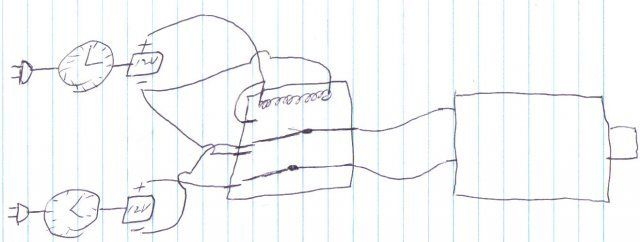
I understand what he was thinking when he said to use 2 diodes. But it wont work. You have power hooked to the same terminal as the ground of the other adapter. You dont have power back feeding in to the other adapter. Its feeding forward from one hot to the other ground. If you block that with a diode the you also block forward flow from its on hot wire.

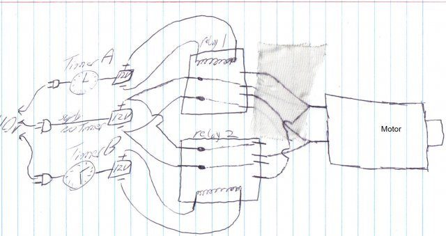
If you used two separate batteries wired threw relays then it may work. Use the same wiring you have now to power the relays in place of the motor. The relays then connect the hot (and ground if ya get duel pole relays) wire from the battery to the motor. Because the battery's are separate systems it should work.

If you use 2 dual pole relays to power the motor so you are switching both the power an ground then you could run it off one power source.
 
18601_lastscan.jpg

Didn't have whiteout so i used tape.
big_smile.png
 
Youch! I'm glad I'm not the only geeky one around here...Just found this thread and I'm very intrigued...going to have to toss in part of my idea:

I've been thinking about a modification on my plexiglass door that would run sideways on inside slots, rather than the up/down exterior slot it's in now, much like what I've seen on many other coop pics around here.

If it was inside tracks, it'd be fairly difficult for a pred to crack, and the mechanical parts would all be inside the coop. My original design was to be some form of a belt system, or chain and gear. I was thinking it could pull it to the side in the morning and then catch it again to close it later. This could easily hit regular light switches as I've seen described in some of the posts, but I'm thinking about dissecting my auto kitty-box when I get my new one and seeing how that reversible motor on tracks does its thing...It's motion activated with a ten minute sensor, so that part'd have to go...

Does this sort of 'pocket-door' approach sound workable?
 
Dave:
That's what I was talking about in this post: https://www.backyardchickens.com/forum/viewtopic.php?pid=1197431#p1197431

The
diodes won't work because no matter how you place them, for the motor to be reversed using two power supplies, there will *always* be a path that connects both supplies together. You're lucky you didn't kill one, or both supplies. Take a look at the schematic diagram I posted, it will show how to wire things together. Let me know if I didn't make the diagram clear enough (sometimes I can't even understand myself :)

Quote:
 
that will work. I was going to do something similar but using a nut and a threaded rod to slide the door instead of chain or cable. I thought of the screw/nut solution because it is auto locking -- can't open the door by pushing it. But once everything is on the inside, a predator couldn't get a grip on the door anyway, and since the screw/nut idea is more difficult (more friction, needs very good alignment so it won't jam), I've decided to use a vertical sliding door lifted & lowered by a cable. I'm in the process of building the mechanical parts right now.

As far as controlling it goes, I have some ready-made hardware that can be adapted to control the motor direction and handle stopping when switches are hit, etc.


Quote:
 
17610_relay1.jpg


This is what I got from Radio Shack. A double pole double throw relay. But I could not get my head around how to configure the wires and make it all work. Its all so confusing to me.
So, I went back to the shack and got two single pole double throw relays, and I am still lost!!

I just have no experience in this kind of thing!
 
OK, lets see if I can explain this.
7 an 8 are the relay power
if there's no power on 7 an 8 then 1 an 5 are connected and 2 an 6 are connected.
If there is power on 7 an 8 then 3 an 5 connect an so do 4 an 6.

So 5 an 6 go to your motor,
power from timer/supplyA goes to 1 an the ground goes to 2,
power from timer/supplyB goes to 3 an 7 an the ground goes to 4 an 8.

Hope that makes sence...
 
Almost there!

I finally grasped how to use a relay in my wiring and pushed forward in the auto-door construction today. Thanks to the BYCers and a smart guy at Radio Shack for being patient and trying to explain how relays work.

I found that my main obstacle was that I didn't really understand how a relay works and was struggling to fit it with my design which was pretty fixed in my mind.

I ended up just needed 1 double pole double throw relay.

Here are some pics to show my progress thus far. Captions are below the photos.

17610_dsc01899.jpg

Here is the motor assembly and wiring to DPDT relay. The PVC houses the motor and relay wiring snuggly. The PVC end caps are drilled for the motor shaft on one side, and the wiring exit on the other.

17610_dsc01900.jpg

Motor in PVC housing. The 1/4" coupler sticks out of the PVC end cap. The wiring is sticking out of the other side. The black electrical tape is a marker for me to know which wire goes where.

17610_dsc01901.jpg

Here's a close up of the motor shaft, coupler, and the spool rod end cap. The spool rod end cap has a hole in it and a short 1/4" screw with a lock washer, and is tightened into the coupler.

17610_dsc01902.jpg

The complete motor package. The spool rod is PVC and will wind up and down the line that connects to the coop door.

17610_dsc01903.jpg

The new chicken coop door. Shown on its side. There is a plywood frame with an opening, and then I used hinges on a piece of fiberglass.

17610_dsc01904.jpg

As I lift the fiberglass door, you can see the frame, large enough for chickens to fit through. I used fiberglass for the door flap because I didn't want it to warp or weather in the rain.

17610_dsc01905.jpg

At the bottom of the frame, I installed magnets, which will hold the door flap tightly against the frame when closed. If you look closely at the bottom right, you can see where I installed the stop switch. When the flap is wound down to shut the door, the stop switch will close the current to the motor.

17610_dsc01906.jpg

Another picture of the door frame and door flap, on its side. You can see the magnets I expoxied to the inside of the door flap.

17610_dsc01907.jpg

Coop door, upright. I screwed on a 2x2 to add some weight to the bottom of the door. This will keep a good amount of resistance on the line as it is wound up and down. And also, when the door flap is closed, it will ensure contact with the magnets, and a good door seal. You can see the wiring of the stop switch on the top right.

That's it for now! Tomorrow I will mount the door frame, and wire up all the timers to the motor, and test test test!

I'll be sure to post more pics and report results too.

Thanks for looking.
 

New posts New threads Active threads

Back
Top Bottom