Just want to tell jthornton and mouthpear thank you so much.

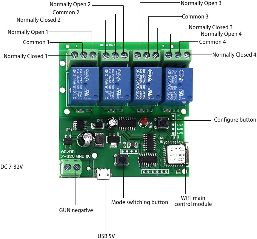
For anyone new going at this project please skip the old timer and relay model that's on the first page. The relay is unreliable. I used both sockets and both relays that plug in, that came with my order from amazon. They eventually stop working. I fiddled and still they would fail.

Look at page 12. I'm using just two timer/relay units wired straight from the battery to the relays how the second schematic shows. I went overboard on solar and got a 25w panel and 20ah battery off amazon. The battery is so big i may go days before the panel needs to charge the battery.

If anybody ever sees this thread and wants a video or list of amazon orders I'll check on this thread for a couple weeks.

PS. if anybody in socal wants to get rid of some reds, I want. My current set of birds are doing ok but I have just medium egg layers. I want some producers now that my coop is secure again. Reds were the best I have ever had. Thanks
 
I used the timer/actuator setup from this thread very successfully in my chicken coop for the last year or so, but got tired of having to adjust the timer every few weeks as the light changed. We only had one unfortunate accident, and luckily the chicken lived. I probably should have built it with the light sensor instead.

Recently I came across a Sonoff type WiFi relay, and with very little effort, got it working with my Home Assistant setup, and from that Apple's HomeKit system via a software bridge. Now I can use Apple's Siri assistant to open and close the door (to impress the neighbors) and I have a HomeKit automation (could be done in Home Assistant) to open the door at sunrise, and close it at sunset).

Here is a video of the system in operation:

And I've attached my best MsPaint impression of the wiring setup and a photo of it in its little waterproof housing.

chicken_door_wiring.png IMG_2919.jpg
 
I used the timer/actuator setup from this thread very successfully in my chicken coop for the last year or so, but got tired of having to adjust the timer every few weeks as the light changed. We only had one unfortunate accident, and luckily the chicken lived. I probably should have built it with the light sensor instead.

Recently I came across a Sonoff type WiFi relay, and with very little effort, got it working with my Home Assistant setup, and from that Apple's HomeKit system via a software bridge. Now I can use Apple's Siri assistant to open and close the door (to impress the neighbors) and I have a HomeKit automation (could be done in Home Assistant) to open the door at sunrise, and close it at sunset).

Here is a video of the system in operation:

And I've attached my best MsPaint impression of the wiring setup and a photo of it in its little waterproof housing.

View attachment 2394066View attachment 2394075

The setup Looks very nice.

This is just FYI for you or other who may want to do this.
Tho If I was to use a module like yours I would use this one.

61iSUrlraIL._AC_SL1000_.jpg


It gives you the capability of stopping the door at any point, not just up or down, using two of the relays. No need for the DPDT relay. It also would give, anyone who want to do it this way, the ability to control another actuator/motor (Ventilation, Sun tracker for solar panel) or two other on/off things such as lights, water pump, feeder or anything else you want to be automated.

BTW I noticed you are using a Raspberry pi. (Looks like it anyway) You could have used the RPi to automatically Adjust the time using one of the Astronomical Time libraries. All you would have need to get was a Motor HAT. I covered using a Motor Hat in this thread.

Thanks for the tips! The Pi is just there to run meye as a chicken monitor with some spare IR cameras I had laying around, but maybe I should have put it to use opening the door instead. :)
 
I am thinking of an implementation using a 2 channel wifi switch. I think this is an easy way to go and the only other items needed are the 12V power supply (3 amps?), the switch and the linear actuator. The switch is available from Ali Express:

https://www.aliexpress.com/item/4000774084464.html

For about $18, I ordered the 12V version with the RF option and remote control for backup (save $3 if you don't want the RF version). This is also available from Amazon. Using Alexa and Samsung SmartThings, I can set up routines to open and close the door based on sunrise and sunset. For example, open at sunset minus an hour and close at sunset plus 30 minutes.

Unlike most designs, my duck coop has a flap door, not a sliding door. It is hinged at the bottom so when open, it becomes a short ramp. I think I can use a 6" stroke actuator mounted vertically on the inside of the coop and attached to the side of the door a few inches from the inside bottom. I will have to do some measuring.
 
When I got chickens for the first time last year, my husband thought I was absolutely crazy as I surprised him with my new little fluff ball babies. I was so excited and had big plans to build them a coop during the time they were in the brooder. About 2 weeks before they were due to make their grand adventure to the great outdoors, 2 of the 4 started fighting and me being me, I panicked and thought they needed more space now. I panicked and very promptly went to Jax Mercantile and bought a cheap-o starter coop, complete with a nesting box and run. Fast forward a few weeks and it turns out, the 2 that were fighting were both Roos! My luck! And now, I was stuck with this silly starter coop until at least next spring. Since they free range, I have no need for their “run” to actually be used as a run... I had been transforming the entire thing into more of an enclosed coop for the winter and I open and shut the door(s) to their “run” every morning and every evening.

I’ve learned a lot this last year with my new babies, but one thing i was not slow to catch onto is that unless you want to take the risk of them being picked off and massacred by creatures of the night, you need to lock them in every night and let them out every morning. What?! I’m an adult! I’ve got things to see and travels to take... I also didn’t want to spend mega bucks on an automatic chicken door, when I have this bizarre makeshift setup going with my starter coop & I can easily transfer it to the new future coop.

I’ll save you the dry information on my challenge figuring out electrical relays and polarity switches but... if you’re a visual person, I made some fun wiring drawings for both a direct power source and solar powered.

Parts Needed:
-JVR 12V Timer Switch Programmable Digital 12 Volt DC/AC Battery Powered Timer - $11.99
http://a.co/d/iYs1EWL

- DC 12V 5A Coil 35mm DIN Rail DPDT 8Pin Power Relay + Socket Base - $11.88 (2 pc - you only need one, so find a 1pc for $6ish if you can!)
http://a.co/d/184sDkI

- Chanzon 12V 5A 60W AC DC Power Supply Adapter (Input 110V-220V, Output 12 Volt 5 Amp 60 Watt) DC Converter - $15.84 (if you already have a power supply, just get a wired connector adapter, for easy connecting/disconnecting)
http://a.co/d/9dGQXSi

- Linear Actuator Motor 750N 12V Dc 200Lbs 305Mm Stroke Electric Door Opener - $35.89 (whatever size you need)
https://www.walmart.com/ip/Linear-A...S-305MM-Stroke-Electric-Door-Opener/959284971

- Electrical Wire & Cutters
- Drill / Screwdriver
- Small Phillips
- Electrical Tape
- Material as needed (door, cabinet sliders, spare wood for frame, etc.)
- Water proof container to store electrical in

TOTAL COST: $75 - You can definitely get away with less if you have some parts laying around, for example the power adapter could come from an old desktop monitor.

*NOTE* - you can also set it up sideways, so it opens and closes side to side instead of up and down, depending on your setup / space constraints.

*NOTE #2* - if any of the links above indicate they are sold out, search the site for the part and there should be more options... usually just a reseller. Th parts listed do not include the solar panel or battery option, so you’ll have to hunt those down if going solar.

Please tag me if you end up making one, I would love to see how it worked out. I posted this tutorial on Facebook back in November and many have already found success in making their own! I’ve been using it since November, and it has held up perfectly through frigid temps and ice/snow here in Colorado.

Hope you find this helpful! Enjoy!
uhg. im trying to do this but my wiring is a mess. I used a different tutorial on YouTube and its different from yours but I can only get it to work one way. something is missing. any advice? Here is what I have going on right now. Also, your diagram is fantastic, however, what do the different color wires mean?
 
uhg. im trying to do this but my wiring is a mess. I used a different tutorial on YouTube and its different from yours but I can only get it to work one way. something is missing. any advice? Here is what I have going on right now. Also, your diagram is fantastic, however, what do the different color wires mean?
I really wish I would have seen this earlier. Almost a year ago. I hope you found your answer. If not, here is a diagram for your specific relay and timer. Or this one.

The issue with yours, as it is in the video, is that you only connected the power wires to terminal (term) 4 (positive red) and term 3 (negative black). What you needed to add is wires to term 2 (negative black) and term 1 (positive red). There is NO "ground". Take that off and use insulated wire.

But I would use this Diagram that uses 2 SPDT timers. There are no external relays to do the switching of the polarity, they are built into the timers. Makes wiring so much easier and saves on battery power. Just FYI.

Diagram 2x TH15A or 2x TM615 timers.

Diagram 2x TH15A timers alt version.

Photo of 2x TH15A timers alt version setup.
 
Last edited:

New posts New threads Active threads

Back
Top Bottom