@Mouthpear

Wow, I guess it's true, there really are a gazillion ways to configure a circuit. Just on the motor/switch side of this little automatic door circuit I can literally think of 32 off the top of my head

Above are four of them. In each of the above I left out the timer switches, or DPDT relay, or whatever we use to send power from the source to the motor in either polarity; to focus on recent discussion, this is just the motor and limit switch portion. In all four, the power "comes" and "goes" through the wires from the bottom.
I have seen examples of
1,
3, and
4. I haven't seen an example of 2, which is the top left or "correct" one in your video. It wouldn't surprise me to learn that they are all over the place, I just haven't seen it yet.
We can get four more configurations by crossing the input lines of each of the above four, like you did in the bottom right one in your video. It's not clear to me why this matters. I'm not saying there isn't an electrical or mechanical benefit one way or the other, I just don't know what that might be.
Instead of SPST switches we could use SPDT switches, as you did and also as in the examples I linked to above, and we could also use Schottky instead of rectifier diodes ... and we're already up to 32 different configurations.
Considerations or potential issues that come to mind are as follows.
EMP: perhaps this isn't as big a concern as it would be if we were switching with, say, BJT transistors or MOSFETS, but is EMP going to come into play with diodes, and does this depend on diode type and proximity of diode to motor, or with direction of diodes?
Heat: Are some configurations more prone to producing excess heat and result in heat-related failure?
Durability: Are some configurations more durable in the conditions in which we wish to implement them than other configurations from, e.g., heat, cold, moisture, etc.? Cheap motors (relatively), tiny electrical components made of thin metal and plastic ... how will they stand up to weather and moisture?
Capacitance-type of discharge: I don't think I have the correct electrical terminology here, but the idea that a backflow of pressure can occur when a circuit is broken by, e.g. a switch, and electrons flow in another direction. Often handled, if I'm not mistaken, by use of properly placed and sized resistors.
I very much favor a circuit where only two rather than six wires go between the power-sending side (e.g. timers) to the motor/limit switch side. For my particular implementation that is beneficial. Others mileage may vary, but for me it is desirable, largely due to the compact space I'm working with. But also because to me, and perhaps this is simply a matter of taste or the way I happen to be setting it up, it offers a more tidy setup. In addition, I believe any of the two-wire versions vs. the six-wire version will pair more nicely with my intended next microprocessor setup.
So, within the realm of having two wires between timers and motor/switches we have the above possibilities (and others ... we could go on and on). I'm not married to my "1" above, I could happily use your "2", and I might. I also like the "linear actuator" type of "one wire to motor one wire to switches" configurations. You say "2" is "correct" ... if you could elaborate further it might help my understanding and make us better informed at choosing between all these configurations. Especially with regards to the above stated considerations.
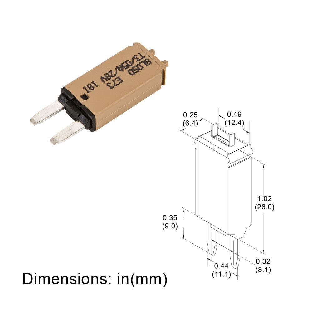
I also will definitely be considering the Schottky diodes .. the small rectifier diodes I used are indeed quite tiny, and the larger size might be better when I get to the soldering.
Finally, I didn't indicate in my diagram in
post #157 which is the upper or lower limit switch. But, as I said above, it's still not clear to me why that matters.


 Time to finally extend our family! Chicken Style!
 Open Contest Cutest Baby Fowl Photo Contest—Win a Brinsea Maxi 48 EX Connect—17th Annual BYC Easter Hatch-Along
 FOOD: what are you having?
 BYC's 52-week Photography Challenge. Week 9: (Mar 2 - Mar 8, 2026) Theme: Frame within a Frame
 Open Contest Egg Candling Photo Contest—17th Annual BYC Easter Hatch-Along