Hack-O-Tronic Thermostat
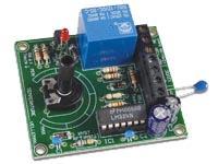
| I am no electronics whizz. I may look like I never see sunlight, but honestly I really am not one of those subterranean experts -- It's just that I live in England. But I did hack together a functional thermostat by adapting the design from a Velleman Kit. It needed a few modifications to make it suitable for use in an incubator. The temperature range was too low (41-86 °F) and the hysteresis (temperature envelope) a little too wide (1.8 °F). I swapped out a few of the components to adjust the temperature range to around 95-105 °F and reduce the hysteresis to just less than 1 °F. If you want to recreate what I did then you could order the kit, load up with a few alternate parts that I have specified below, and just follow the instructions. With a bit of artistry you might end up with an extremely pretty object like the one on the right. | 
|
The schematic for the original kit looks like this. It may look like spaghetti with clams but I am told that it is pretty straightforward to put together, if you have a soldering iron and a couple of hours to spare. I suggest the following modifications. First, change resistor R5 from 120 kΩ to 33 kΩ. This raises the temperature range. Second, change the potentiometer RV1 from 100 kΩ to 10 kΩ. This gives a narrower temperature range so that fine adjustments are easier to make. Third, change resistor R7 from 6.8 MΩ to 10 MΩ. In combination with the other two changes, this reduces the hysteresis of the thermostat. A further change that you will want to make is to attach long wires to the thermistor so that it can be used as an extended probe.

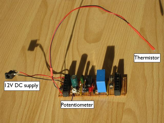
Now instead of doing the straightforward thing, I cobbled something up using some of the bits and pieces of electronics that are heaped on my desk. Naturally this took a long time but gave me a laborious sort of satisfaction. (Fellow hackers please PM me if you want to know the stripboard layout that I used.) I had most of the parts handy -- you know, in a pile somewhere under a few things -- so all I needed to buy was the temperature sensor, called a thermistor (Maplin order code CR05F). The thermistor had a different specification than the one used in the original kit, so I switched resistor R4 from 10 kΩ to 100 kΩ to match it. If you just use the thermistor that comes with the kit, you should not need to change resistor R4. I also decided to use a relay that could handle mains power and put a 5A fuse on the output, in case I wanted to use a normal incandescent bulb. (I opted not to in the end, primarily for safety reasons). My mongrel artifact came out looking like this. A bit rustic, but we're engaged in agriculture here, right? When I got around to putting it in a box I did change one thing. I swapped the fiddly little trimmer potentiometer for one with a large knob. The bigger the better, right? And I have calibrated it and it works just fine for me.

Lastly, a disclaimer. Careless use of hot soldering irons/electrical gadgets may burn down your house/zap your chicks. Happy hacking!
Recommended Parts List:
Velleman MK138 thermostat kit
33 KΩ resistor
10 MΩ resistor
10 KΩ potentiometer (with spindle for ease of use, or multiturn potentiometer to allow fine tuning)
A box to put it in (optional)
You will also need:
Soldering iron and solder (for electronics not plumbing!)
Hook up wire
Postscript
I subsequently found out that last year's incubator contest winner used a similar thermostat hack that allows even smaller hysteresis, perhaps as low as 0.4 °F. The smaller hysteresis should in theory allow greater temperature stability, which is generally preferable. The drawback is that the thermostat cycles on and off more quickly which will tend to shorten the life of the bulbs. This can happen especially if the thermistor and heat source are close together as in my homemade incubator. When I tried the values used in this low hysteresis set up (R4 = 4.7 kΩ; R5 = 3.9 kΩ; R6 = 2.7 kΩ; R7 = 10 MΩ; 1 kΩ potentiometer) the thermostat short cycled with an irritating buzz. I found that reducing R7 to 3.3 MΩ and soldering a 100 μF capacitor between ground and the connection of R3 and T1 minimized flicker and eased the transition between on and off states. With this modification, I was able to get the air temperature in my incubator to cycle smoothly between 37.4 °C (99.3 °F) and 37.6 °C (99.7 °F).
