Microwave Incubator Build
Step 3. Timer
I borrowed the concept for the electronic timer from here -- refer to this webpage for a description of how the circuit works. I made the following substitutions:
| |
| |
|
Here is my schematic (click thumbnail for full size image):

And the corresponding stripboard layout:

One final adjustment: to shorten the interval between turns I removed the link from strip 5 to pin 3 of U1 and reconnected it between strip 5 and terminal 15 of Q1. I adjusted the potentiometers VR0 and VR1 so that LED D0 flashed every minute or so and the relay turned on for a 10 second burst every hour.
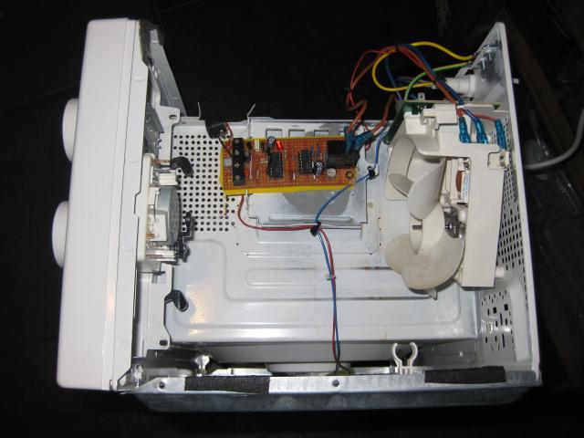
Here is the completed timer circuit in situ. There is a slip of yellow plastic behind the board to insulate the solder connections on the back. The brown wires connect the live terminals on the noise filter PCB (on top of the fan assembly) and the fan, via the relay. The blue return wire from the fan is plugged directly onto the neutral terminal on the PCB. When the timer triggers the monostable, the relay will turn on both the fan and the turntable. The fan turning on is just a side effect of wanting to turn on the turntable so I could have removed the blades. On the left hand side of the timer board, a barrel adapter for the 12 V supply is connected to the terminal block.
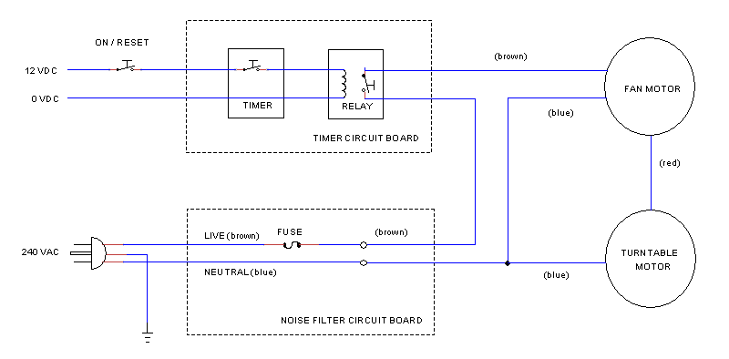
Here is a simplified schematic showing how the timer, fan, and turntable motor are connected up. The fuse and ground connection (to the microwave casing) are essential features of the mains supply which is 240 VAC in the UK. I put a switch on the 12 V supply to the timer circuit so that the turner can be switched off during lockdown. (The same thing could be achieved by unplugging the mains.) The switch doubles as a timer reset because turning the timer off and on again resets the timer. So I ended up not using the terminal connections on the timer board that allow for a reset switch.
Parts list:
74HC4060 14 stage binary ripple counter with oscillator
CD4013 dual D-type flip flop
LM78L05 voltage regulator
LED
2x 1N4148 diodes
BC337 NPN transistor
240V SPST relay (from microwave oven)
NO momentary contact switch
1 kΩ, 4.7 kΩ, 10 kΩ, 150kΩ resistors
100 kΩ, 220 kΩ variable resistors
10 nF, 2x 100 nF, 330 nF, 10 uF, 47 uF, 220 uF capacitors
stripboard (AKA veroboard)
terminal blocks
16 pin and 14 pin DIP sockets (optional)
I also needed:
Soldering iron (25 W)
Solder (multicore 0.7mm)
Hook up wire
Wire strippers/clippers
Next Step
Previous Step
Back to Microbator Plan