Automatic Chicken Coop Door - Auto Closes Coop - Beta Version 1.0

Pics
Hi folks, great ideas going around in this thread. I'm a first time chicken owner here, my babies are 4 weeks old and the coop is about 80% done. I tapped my soon to be father-in-law who is a retired Mechanical Engineer for a door that will automatically close on a timer. I didnt even think to go as far as asking him to design me something that will both open and close it. Thats next:) Heres a couple pics that he emailed me of what he threw together in an afternoon. I get it delivered Thanksgiving day! I'm thinking thats the day my 25 RIR's get to move into their main home. Anyway, nice meeting all you chicken nuts, the Fiance and I are already addicted to our chicks and talking about getting an assorted batch of 25 come Spring.....Geo

Pictures should be clickable


Last edited:
So far, I have got a nice high torque motor that I will use for one of two open/close methods.

1. The one that requires the least changes to my current door, a vertical swing open door. The motor will reel up a line that opens the door (outwards), and then to close it, it will unreel the line in the opposite direction.

2. A threaded rod design, where the motor winds the rod which moves the door which is mounted on a sliding track.


The motor is 12vDC. So far, I have thought of a way to control the direction of the motor. I would have two 12v power adapter connected to the motors with the wires in opposite positions. So current from one power source would turn it clockwise, and from the other, counterclockwise. Each power adapter would be plugged into their own timer which would trigger the opening/closing of the door by opening up the current to the motor.

There might be another way to do what I've just explained, through circuitry, or relays, whatever. But I am afraid I don't have the experience or expertise to incorporate these things, yet.

One thing I have not figured out is how to STOP the motor when the door has opened, and when to stop the motor when the door has closed.

Maybe someone can suggest a way I incorporate an interrupting switch, perhaps by contact at the doors most open state, or closed state.


The motor runs at 5rpm, pretty slow. This could potentially be an advantage and a disadvantage to the threaded rod design. I think because of the rotation speed, it will take a long time for the door to open and close. Maybe if the time it takes to open/close is the same as one of the timer increments, I can just use the timers as start/stops for the motor. But the timers are not digital, and I fear it would be risky to depend on the imprecision of these timers.

Help appreciated!

Dave
 
dave,

my idea was just to put a couple of plain old house light switches at each end of the door's swing, when the door hits it, it turns off the current.

pulling a line i'm not sure how this could be accomplished, maybe run the line through some washers attached to the light switch (or drill holes in the switch) with a knot in the line that toggles the switch or something like that.

with the threaded rod it's easier to just have it push the switch off and on

manual reset


also i don't know if you noticed earlier, but harbor freight has digital timers for about 8 bucks, if you don't have one in eugene, i could get some for you here.
 
Last edited:
Quote:
We do have a harbor freight. I'll go check out the timers.

I see your point on the switches. The thing is, I don't want the switch to permanently turn off the current. Because I want it to work again on the next cycle.
 
i THINK

i'd have to draw it out to be sure, but if you have 2 switches with two current directions, the open could be used to turn on the close. the timer would still command the actual current, but the switch i THINK could be reset this way
 
You could usa a "momentary" push switch (radio shack has them) so there is only power when the switch is NOT pushed (get the correct one).

You could also mechanically make one. Have two pieces of copper, or stainless steel if you want to avoid any corrosion, touching and have the door push the pieces apart when it is in the position you want. Do the same thing on the other side with the other adapter.

Process:

In the morning:
Timer 1 turns on and powers the door for 2 mins.
The door slowly opens and gets to the "limit switch" which cuts power to timer 1

In the evening:
Timer 2 turns on and powers the door for 2 mins in the other direction.
The door slowly closes and gets to the "limit switch" which cuts power to timer 2

No manual resetting needed, but you would need 2 timers and 2 adapters.
 
Thanks guys. I am working on it. I'll report results soon.
smile.png
 
Dave:
I don't think that will work. Here's the problem:
if you have two power sources connected to the motor so each would drive it in another direction, there is also a path that shorts them together and that's where most of the current will go, instead of through the motor.

The only way to avoid this would be to have your limit switches tied together so as soon as one opened, the other closed, but they could never both be closed at the same time. With a limit switch at each end, if the door is in the middle and the switches aren't connected mechanically, they will both be in the ON state and so will short out your power.

Here's a sample schematic diagram using relays that will drive the door in either direction. Assume that the switches shown are at each end of the door travel and normally ON. Activating one of the control inputs will run the door until it hits the limit which will turn it OFF. Activating the other input will run the door in the other direction.

coopdoor.png


To activate either direction, you would connect the input shown to + battery terminal. The relays are inexpensive Single Pole Double throw relays (most common type) and the switches are limit switches. I don't remember what they cost but I have had dozens of them sitting in storage just waiting for such an opportunity :)

I plan on doing something like this, but I haven't worked out exactly what just yet.

Hope that helps.
 
So, today I spent some time working on the threaded rod design.
I felt pretty successful overall, however, I think I still prefer working with the vertical flap door design, which is currently how my coop door works.
17610_dsc01870.jpg


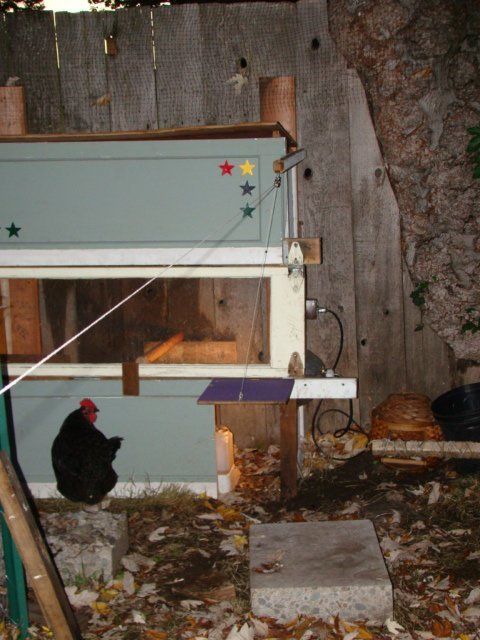
Below, you can see how I put the thread rod design together. It was all pretty make-shift, because I didn't want to make anything really permanent if I wasn't sure which design to focus on. Two nuts hold the rod in place on a board with zip ties. I used some plastic as a spacer to get some space between the rod and the board. This was mainly to accommodate the position of the motor shaft.
I used some pvc to "house" the motor on one side, and then cut and melted flat the same peice of pvc to mount the housing to the sliding mechanism, which was screwed into the board below the threaded rod.

I wired the motor and tested the design just to see how it worked. I didn't apply any of the switch mechanisms or timers. I spent a lot of time figuring out how to get the motor shaft to turn the rod. I found a small nut that could be wedged into the large nut that fit the rod. I hammered it in, then used a dremel tool to shape the inside of the smaller nut to hold the motor shaft.

Pics:
17610_dsc01871.jpg

17610_dsc01872.jpg


I built it onto this piece of plywood so I could put it all together. I suppose I could just screw this plywood to the inside of the chicken coop. The door would be mounted on the sliding track, on the left side of the motor. All the gear you see would be on the inside of the coop. I suppose if I really wanted to, I could have the gear side facing the inside of the coop wall so there would be less chance of dirt and chicken poo interfering.

I went to an electronics store today and found a switch that will help me cut the current and stop the motor when appropriate.
It's called a mini snap action switch:
17610_dsc01873.jpg

'
I bought two of them, for an open stop and a close stop. These switches can be incorporated into both designs.

So, the motor I have runs at 5 rpm. Its relatively slow for the thread rod design. I didn't time the rate in which the door would open or close with the thread rod design. But I am sure the vertical door (flap) design with a winding string would be much faster with the same motor.

One potential advantage to a slow open and close is that maybe I could omit the action switches because I could use timers that would cut the power.

So, I'd be curious to hear what everyone thinks of my observations and design.

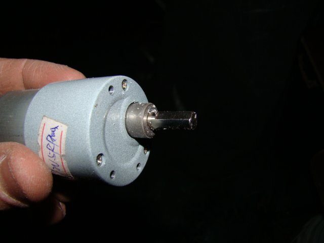
Also, if anyone has experience using motors, I am curious about my options for hardware that fits the motor shaft. I attached a picture. Its about 80% round with 15-20% flat.
17610_dsc01874.jpg


I will try to work with the vertical flap door design tomorrow. I would like to just use 4-6" of PVC as a dowel to wind the string on. I tried dremeling out a hole on a PVC end piece but it didn't really have much grip. I suppose I can just epoxy the shaft to the pvc end piece, but I am a little hesitant because I want to be able to change the design if necessary. Maybe I should just buy another motor!
smile.png


Thanks guys!
 

New posts New threads Active threads

Back
Top Bottom